
User Guide


Garmin G1000 Pilot’s Guide for the Columbia 350/400
190-00552-00 Rev. A4-12
AUDIO PANEL AND CNS
DATA LINK RECEIVER XM RADIO SYSTEM
When no external entertainment music is connected to the Audio Panel through MUSIC 1 and MUSIC 2
jacks, audio from the Data Link Receiver may be heard by the pilot and passengers simultaneously (optional:
requires subscription to XM Audio Service).
Connecting a stereo input to either MUSIC 1 or MUSIC 2 removes the Data Link Receiver Audio from that
input. For example, if passengers prefer music while the pilot listens to the Data Link Receiver, the entertainment
audio would be connected to the MUSIC 2 jack.
Refer to the Additional Features Section for more details on the Data Link Receiver.
CLEARANCE RECORDER AND PLAYBACK
The Audio Panel contains a digital clearance recorder that plays back up to 2.5 minutes of COM signal
recording. Recorded COM audio is stored in separate memory blocks. Audio from the selected COM radio is
recorded and can be played back. Quiet periods between COM reception is not recorded. Anyone able to hear
the selected COM radios is able to hear the COM audio playback.
Once the 2.5 minutes of recording time have been reached, the recorder begins recording over the stored
memory blocks, starting from the oldest block. Powering off the unit automatically clears all recorded blocks.
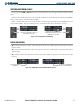
The
PLAY
Key controls the playback function.
• Pressing the
PLAY
Key once plays the latest recorded memory block, then returns to normal operation.
• Pressing the
PLAY
Key again during playback of a memory block plays the preceding recorded block. Each
subsequent press of the
PLAY
Key will backtrack through the recorded memory blocks to reach and play any
desired block.
• Pressing the
MKR/MUTE
Key during playback halts playback and returns the recorder/playback to normal
operation.
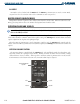
Figure 4-9 Playback Key
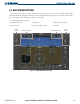
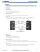
REVERSIONARY MODE
The red DISPLAY BACKUP Button selects the Reversionary Mode for both displays. Reversionary Mode
operation displays important flight and engine information on both the PFD and MFD, in case of display failure.
See the System Overview section for more information.
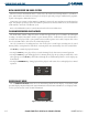
Figure 4-10 Reversionary Mode Button