
User Guide


190-00552-00 Rev. A
Garmin G1000 Pilot’s Guide for the Columbia 350/400
2-11
FLIGHT INSTRUMENTS
Upon station passage, the TO/FROM indicator flips and points to the tail of the aircraft, just like the
conventional TO/FROM flag. Depending on the navigation source, the CDI on the Arc HSI can appear in two
different ways: an arrowhead (GPS, VOR, OBS) or a diamond (LOC).
HEADING AND COURSE INDICATIONS
NOTE: See the AFCS Section for more information on Selected Heading functions.
A digital reading of the current magnetic heading appears on top of the HSI. The heading displayed on the
HSI is always magnetic, even if the NAV ANGLE is set to ‘TRUE’ on the AUX - System Setup Page on the MFD
(see the System Overview for details).
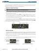
When the pilot selects a course by rotating the
CRS Knob, a digital reading appears for three seconds in a
box to the right of the lubber line, next to the HSI. Pressing the CRS Knob displays the digital reading, re-
centers the CDI, and returns the course pointer TO the bearing of the active waypoint or navigation station
(see OBS Mode for information on adjusting a GPS course).
When the pilot selects a heading by rotating the
HDG Knob, a digital reading appears for three seconds in a
box to the left of the lubber line, next to the HSI. A rotatable heading bug marks the desired heading on the
HSI. This Selected Heading Bug and the current aircraft heading can be synchronized by pressing the HDG
Knob, which moves the bug to the current heading.
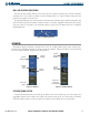
Figure 2-16 Heading and Course Indications
Selected
Heading
Selected
Course
Current
Heading
Selected
Heading Bug
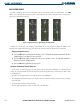
TURN RATE INDICATOR
The Turn Rate Indicator is located directly above the rotating compass card. Tick marks to the left and right
of the lubber line denote half-standard and standard turn rates. A magenta Turn Rate Trend Vector shows the
current turn rate. The end of the trend vector gives the heading predicted in six seconds, based on the present
turn rate. At rates greater than 4 deg/sec, an arrowhead appears at the end of the magenta trend vector and
the prediction is no longer valid (Figure 2-17).
A standard-rate turn is shown on the indicator by the trend vector stopping at the standard turn rate tick
mark, corresponding to a predicted heading of 18˚ from the current heading (Figure 2-18).
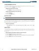
Figure 2-17 Turn Rate Indicator and Trend Vector
Half-Standard Turn
Rate Tick Mark
Standard Turn
Rate Tick Mark
Turn Rate
Trend Vector
(Rate > 4
deg/sec)
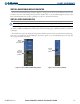
Figure 2-18 Standard-Rate Turn Indication
Turn Rate
Trend Vector
(Standard Rate)