GHP™ 10 Marine Autopilot System Installation Instructions To obtain the best possible performance and to avoid damage to your boat, install your GHP 10 marine autopilot system according to the following instructions. Read all installation instructions before proceeding with the installation. If you experience difficulty during the installation, contact Garmin Product Support, or seek the advice of a professional installer.
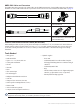
GHP 10 Package Contents and Tools Needed The GHP 10 autopilot system consists of multiple components. Familiarize yourself with all of the components before beginning installation. You must know how the components operate together in order to correctly plan the installation on your boat. As you familiarize yourself with the GHP 10 components, confirm that your package includes the following items. All the components except for the hydraulic pump are included in the GHP 10 core box.
The GHC 10 Use the GHC 10 to operate the GHP 10 autopilot system. Using the GHC 10, you engage and steer the GHP 10. You also set up and customize the GHP 10 using the GHC 10. The GHC 10 connects to a NMEA 2000 network to communicate with the CCU and with an optional NMEA 2000-compatible GPS device (to use waypoint and route information). If a NMEA 2000-compatible GPS device is not available, you can wire the GHC 10 to an optional NMEA 0183-compatible GPS device instead.
NMEA 2000 Cables and Connectors The NMEA 2000 cables connect the CCU and the GHC 10 to the NMEA 2000 network. Use the NMEA 2000 power cable and two terminators to create a NMEA 2000 network on your boat if one does not exist. For more information on NMEA 2000, see page 21. NMEA 2000 drop cable, 6 ft.
Installation Preparation Before installing the GHP 10 autopilot system, it is important for you to completely understand where all the components will be located on your boat. Temporarily place all the components where you plan to install them. Ensure that all cables and hydraulic hoses can reach the necessary components before mounting any components. Hydraulic Considerations – 2.0 L and 1.
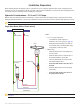
Dual-Helm Boats Balanced cylinder Starboard fitting Port fitting Upper helm PRS Lower helm 2.0 L/1.2 L pump (and motor) PRS Shadow drive Port line Return line Starboard line Notes: • 2.0 L/1.2 L pump (and motor): ◦ An unbalanced cylinder requires an unbalanced valve on the pump (See page 30) ◦ Mount the pump horizontally if possible. Do not mount the pump vertically with the pump end (hydraulic connections) down. • Shadow Drive ◦ Mount the Shadow Drive horizontally and as level as possible.
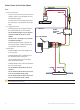
SeaStar Power Assist-Enabled Boats Notes: Return line Starboard line • Power Assist module: Return line ◦ It may be necessary to remove the Port line Power Assist module to gain access Shadow drive to the fittings, the hoses, and the bleed-tee fitting. S RP ◦ Remove the bleed-tee fitting from the Power Assist module and relocate it to the return port on the pump. Helm • 2.0 L/1.
Hydraulic Considerations – 2.1 L Pump Different boats have different hydraulic considerations you must examine before mounting the pump or cutting any hoses. Before starting the hydraulic installation, verify the type of hydraulic steering in your boat, and where to install the appropriate type of pump. Caution: If the hydraulic steering of your boat does not match the hydraulic layouts in this manual, contact Garmin Product Support.
Dual-Helm Boats Balanced cylinder Starboard fitting Port fitting Upper helm 2.1 L pump (and motor) Lower helm PRS PRS Shadow drive Port line Return line Starboard line Notes: • 2.1 L pump (and motor): ◦ Do not use the 2.1 L pump on a system with an unbalanced cylinder. ◦ Mount the pump horizontally if possible. Do not mount the pump vertically with the pump end (hydraulic connections) down. • Shadow Drive ◦ Mount the Shadow Drive horizontally and as level as possible.
SeaStar Power Assist-Enabled Boats Starboard line Return line Port line Notes: • Power Assist module: ◦ It may be necessary to remove the Power Assist module to gain access to the fittings, the hoses, and the bleed-tee fitting ◦ You may need to add a tee fitting in the return line at the Power Assist module to connect the pump. • 2.1 L pump (and motor): ◦ Install the pump to the steering lines between the cylinder and the Power Assist module.
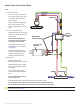
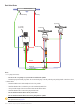
Electrical/Data Connection and Mounting Considerations The GHP 10 components connect to each other and to power using the included cables. Ensure that the correct cables reach each component, and that each component is in an acceptable location, before mounting any components. Read the following considerations and consult the diagram on the next page before you begin installation. The Pump and the ECU • The pump must be located within 19 in. (0.5 m) of the ECU, mounted horizontally if possible.
Yellow CCU signal wire (see page 20) GHC 10 Red (+) Black (-) 8-32 Vdc 1 A fuse Ignition or in-line switch Red (+) Black (-) NMEA 2000 network (see page 21) Drain (-) NMEA 2000 power cable CCU ECU POWER Red (+) Black (-) Pump (2.1 L pictured) CCU 12 Vdc 40 A fuse PUMP ENCODER For CCU bare-wire connections, see page 17.
Installation Procedures After you have completely planned the GHP 10 installation on your boat, and have satisfied all the hydraulic, mounting, and wiring considerations for your particular installation, you can begin mounting and connecting the components. Installing the Pump (and Motor) Install the pump by mounting it on your boat, connecting it to the hydraulic steering lines of your boat, and connecting it to the ECU. If your boat uses an unbalanced-cylinder steering system, be sure you have a 2.
To connect the pump to the hydraulic lines: 1. Consult the hydraulic layout diagrams starting on page 5 to find the correct place to connect the pump to your hydraulic system. 2. Prepare to disconnect the hydraulic lines in your boat as specified by the manufacturer of your boat or steering system. 3. Disconnect the hydraulic lines from the steering system where appropriate. 4. Add additional hose where necessary, and add the included t-connectors in the hydraulic lines. 5.
Connecting the 2.1 L Pump to the Hydraulic Lines The 2.1 L pump must be isolated from the electrical ground of the boat. Use insulating washers under the pump if it is installed on an electrically-grounded (metal) surface. Install the washers between the pump bracket and the grounded surface Before disconnecting any hydraulic lines on your boat, consult the manufacturer of your boat or steering system.
Installing the Electronic Control Unit (ECU) To install the ECU, mount it to your boat, connect it to the pump and to the CCU, and wire it to the boat battery. Mounting the ECU Mount the ECU horizontally on a flat surface within 19 in. (.5 m) of the pump. The cables from the pump cannot be extended. Mount the ECU in a location where you can run wire to the boat battery, but do not connect it to the battery at this time. The power wire can be extended, if necessary.
To secure the CCU in the CCU bracket: 1. Connect the CCU/ECU interconnect cable and the NMEA 2000 drop cable to the CCU. 2. Place the CCU in the mounting portion of the CCU bracket with the wires hanging straight down, toward the water. 3. Place the securing portion of the bracket over the ball and snap it into the mounting portion of the bracket, starting with the two arms that do not have the thumbscrew. 4. Make sure the cables hang straight down, toward the water, and connect the arm with the thumbscrew.
Wiring the GHP 10 to the Tachometer The tachometer connection is an important part of the GHP 10 system, and must be wired correctly for the autopilot to function. If your engine supports NMEA 2000 engine data, and is connected to the same NMEA 2000 network as the GHC 10 and the CCU, then no other tachometry wiring is necessary. For more information on the NMEA 2000 network, see page 21.
Installing the GHC 10 Install the GHC 10 by flush-mounting it in the dashboard near the helm, connecting it to power and to the yellow CCU signal wire from the CCU/ECU interconnect cable, and connecting it to a NMEA 2000 network. Optionally, you can connect the GHC 10 to a NEMA 2000 or NMEA 0183-compatible GPS device to use waypoint and route data. Mounting the GHC 10 Flush mount the GHC 10 in the dashboard near the helm.
Wiring the GHC 10 to Power and to the CCU/ECU Interconnect Cable With the GHC 10 power/data cable, wire the GHC 10 to power and to the yellow CCU signal wire on the CCU/ECU interconnect cable. Optionally, you can wire the GHC 10 power/data cable to a NMEA 0183-compatible GPS device to use waypoint and route information with the GHP 10, although a NMEA 2000 GPS device is preferred. To wire the GHC 10 to power: 1. Route the GHC 10 power/data cable to the boat battery. 2.
Connecting the GHC 10 to a NMEA 2000 Network Connect the GHC 10 to the CCU through your existing NMEA 2000 network. If you do not have an existing NMEA 2000 network on your boat, all the parts needed to build one are supplied in the GHP 10 package. Optionally, you can connect a NMEA 2000compatible GPS device to your NMEA 2000 network to use waypoint and route information with the GHP 10. For more information on NMEA 2000, visit www.garmin.com. To connect the GHC 10 to your existing NMEA 2000 network: 1.
3. Add the included T-connector for the CCU in the NMEA 2000 network by connecting it to the side of the T-connector you disconnected. 4. Route the included drop cable to the bottom of the T-connector you just added to your NMEA 2000 network. If the included drop cable is not long enough, you can use a drop cable up to 20 ft. (6 m) long (not included). 5. Connect the drop cable to the T-connector and the CCU. 6.
Connecting an Optional GPS Device to the GHP 10 Autopilot System Connect an optional GPS device to the NMEA 2000 network to use waypoint and route information with the GHP 10. Alternatively, you can connect a NMEA 0183-compatible GPS device to the GHC 10 to use waypoint and route information with the GHP 10. To connect an optional NMEA 2000-compatible GPS device to your GHP 10: 1. Add an additional T-connector (not included) for the optional GPS device you want to add to the NMEA 2000 network. 2.
Making the Final Power Connections After all the components are mounted, connected to the hydraulics of your boat, and wired correctly, connect the ECU to the boat battery and connect the power/data cable to the GHC 10. Use the checklist provided in the back of this manual to ensure that the preceding installation procedures are complete. Connect the ECU power cable directly to the boat battery if possible.
Configuring the GHP 10 The GHP 10 must be configured and tuned to your boat dynamics and motor configuration. Use the Dockside Wizard and the Sea Trial Wizard on the GHC 10 to configure the GHP 10. These wizards will walk you through the necessary configuration steps. Advanced Configuration Power-on Procedure Neither the wizards nor the advanced configuration options are available on the GHC 10 under normal conditions.
2. Planing RPM: Take note of the RPM reading from the tachometer on the dashboard of your boat at the point your boat transitions from displacement to planing speed. If the tachometer value does not match the value on the GHC 10, use the arrows to adjust the value. When you are finished, select Done. 3. Calibrate Compass: Follow the directions on the GHC 10. Drive your boat in a straight line, and select Begin when you are ready.
Category Setting Description Tachometer Setup Planing RPM Take note of the RPM reading from the tachometer on the dashboard of your boat at the point your boat transitions from displacement to planing speed. If the value does not match the value on the GHC 10, use the arrows to adjust the value. Tachometer Setup Low RPM Limit Take note of the RPM reading from the tachometer on the dashboard of your boat at the lowest RPM point.
Appendix Specifications ECU Physical Dimensions (W×H×D): Weight: Temperature Range: Case Material: Power Cable Length: Power Input Power: Fuse: Main Power Usage: 619/32 in. × 419/32 in. × 2 in. (167.6 mm × 116.8 mm × 50.8 mm) 1.5 lb. (0.68 kg) from 5°F to 131°F (from -15°C to 55°C) Fully gasketed, high-impact aluminum alloy, waterproof to IEC 529 IPX7 standards 9 ft. (2.7 m) 11.
Shadow Drive Dimensions (L × Diameter): Weight: Temperature Range: Cable Length: Alarm Buzzer Dimensions (L × Diameter): Weight: Temperature Range: Cable Length: 219/32 in. × 15/16 in. (66 mm × 33 mm) 1 lb. (0.45 kg) from 5°F to 131°F (from -15°C to 55°C) 9 ft. (2.7 m) / in. × 1 in. (23 mm × 25 mm) 2.4 oz. (68 g) from 5°F to 131°F (from -15°C to 55°C) 10 ft. (3.
CCU Receive Transmit 059392 ISO Acknowledgment 059392 ISO Acknowledgment 059904 ISO Request 059904 ISO Request 060928 ISO Address Claim 060928 ISO Address Claim 126208 NMEA - Command/Request/Acknowledge Group Function 126208 NMEA - Command/Request/Acknowledge Group Function 126464 Transmit/Receive PGN List Group Function 126464 Transmit/Receive PGN List Group Function 126996 Product Information 126996 Product Information 127258 Magnetic Variation 127250 Vessel Heading 127488 E
Mounting Templates Use the following mounting templates to assist with the mounting process.
GHP 10 Marine Autopilot System Installation Instructions
1.2 L/2.
2.
GHP 10 Installation Checklist Detach this checklist from the installation instructions and use it to assist with the GHC 10 installation process. Read all installation instructions before installing the GHC 10. Contact Garmin Product Support if you have any questions during the installation process. 1. Refer to the charts starting on page 5 for the proper locations of the pump, Shadow Drive, and other hydraulic requirements.
© 2008 Garmin Ltd. or its subsidiaries All rights reserved. Except as expressly provided herein, no part of this manual may be reproduced, copied, transmitted, disseminated, downloaded or stored in any storage medium, for any purpose without the express prior written consent of Garmin.