
Cockpit Reference Guide

Garmin G1000H
™
Cockpit Reference Guide for the Bell 407GX
190-01254-00 Rev. B
7
Engine Indication & Crew Alerting System
Flight
Instruments EICAS
Nav/Com/
XPDR/Audio AFCS GPS Nav
Flight
Planning Procedures
Hazard
Avoidance
Additional
Features
Abnormal
Operation
Annun/
Alerts Appendix Index
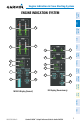
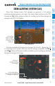
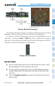
ENGINE POWER AND SPEED INDICATIONS
Power Situation Indicator Gauge and Dual Tachometer Gauge
Maximum Continuous
Power Operation Limit
Power Available
Indicator
NG Readout
MGT Readout
Box Indicates Parameter
Controlling PSI Indicator
NP Indicator
NR Readout
NR Indicator
Torque Readout
Power Available Gauge
Dual Tachometer Gauge
Power Situation Indicator
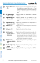
The PSI provides the pilot with the amount of power available based on engine
torque (Q; shown as a percentage), measured gas temperature (MGT, degrees Celsius,
°C), and gas producer rotation speeds (NG; shown as a percentage) with respect to
operating limitations. In normal conditions, a green box is shown around the label for
the readout currently closest to its maximum continuous power (MCP) limits. This
value also controls a green pointer along a numeric scale from 0 (no power) to 10
(MCP, shown with a red tick mark).
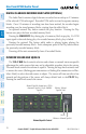
Operating limits are displayed along the PSI gauge and are calculated dynamically
in response to all parameters, to show the range of needle movement available beyond
MCP before any parameter reaches the operating limit. Green arcs indicate continuous
operation ranges; yellow arcs indicate transient operating limits. A gray arc becomes
red if the Power Available Indicator enters this range; it indicates an exceedance is
occurring.
During engine start, a red triangle appears on the PSI arc when MGT is shown to
correspond with MGT starting limits, and remains displayed until the starter has been
disengaged for 5 seconds.
Takeoff Timer
After the engine has been started, if Q or MGT are within the takeoff limitation
ranges, the G1000H displays a 5-minute countdown timer inside the PSI gauge. The