G1000H™ Integrated Flight Deck Cockpit Reference Guide for the Bell 407GX
FLIGHT INSTRUMENTS EICAS NAV/COM/TRANSPONDER/AUDIO PANEL AUTOMATIC FLIGHT CONTROL SYSTEM GPS NAVIGATION FLIGHT PLANNING PROCEDURES HAZARD AVOIDANCE ADDITIONAL FEATURES ABNORMAL OPERATION ANNUNCIATIONS & ALERTS APPENDIX INDEX
Copyright © 2011 Garmin Ltd. or its subsidiaries. All rights reserved. This manual reflects the operation of System Software 1237.03 or later for the Bell 407GX. Some differences in operation may be observed when comparing the information in this manual to earlier or later software versions. Garmin International, Inc., 1200 East 151st Street, Olathe, Kansas 66062, U.S.A. Tel: 913/397.8200 Fax: 913/397.8282 Garmin AT, Inc., 2345 Turner Road SE, Salem, OR 97302, U.S.A. Tel: 503/391.3411 Fax 503/364.
warrant or make any representations regarding its accuracy, reliability, or otherwise. Under no circumstances including negligence, shall AOPA be liable for any incidental, special or consequential damages that result from the use or inability to use the software or related documentation, even if AOPA or an AOPA authorized representative has been advised of the possibility of such damages.
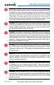
Warnings, Cautions & Notes WARNING: Navigation and terrain separation must NOT be predicated upon the use of the terrain avoidance feature. The terrain avoidance feature is NOT intended to be used as a primary reference for terrain avoidance and does not relieve the pilot from the responsibility of being aware of surroundings during flight. The terrain avoidance feature is only to be used as an aid for terrain avoidance. Terrain data is obtained from third party sources.
Warnings, Cautions & Notes WARNING: Do not use datalink weather products (e.g., XM WX Satellite Weather, GFDS World Wide Weather, or FIS-B) for hazardous weather penetration. Weather information provided by these products is aged by up to several minutes and may not depict actual weather conditions as they currently appear. WARNING: Use of the Stormscope is not intended for hazardous weather penetration (thunderstorm penetration).
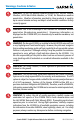
Warnings, Cautions & Notes WARNING: The illustrations in this guide are only examples. Never use the G1000H to attempt to penetrate a thunderstorm. Both the FAA Advisory Circular, Subject: Thunderstorms, and the Aeronautical Information Manual (AIM) recommend avoiding “by at least 20 miles any thunderstorm identified as severe or giving an intense radar echo.” WARNING: Lamp(s) inside this product may contain mercury (HG) and must be recycled or disposed of according to local, state, or federal laws.
Warnings, Cautions & Notes NOTE: All visual depictions contained within this document, including screen images of the G1000H panel and displays, are subject to change and may not reflect the most current G1000H system and aviation databases. Depictions of equipment may differ slightly from the actual equipment. NOTE: This device complies with part 15 of the FCC Rules.
Record of Revisions Part Number 190-01254-00 Rev A Change Summary Initial release. Revision Date of Revision Affected Pages B September, 2011 All 190-01254-00 Rev. B Description Update SiriusXM product references Updated Iridium registration procedure Added other GDU 12.
Record of Revisions Blank Page RR-2 Garmin G1000H™ Cockpit Reference Guide for the Bell 407GX 190-01254-00 Rev.
Table of Contents FLIGHT INSTRUMENTS................................................................................................................. 1 Selecting the Altimeter Barometric Pressure Setting....................................................... 1 Selecting Standard Barometric Pressure (29.92 in Hg)..................................................... 1 Change Altimeter Barometric Pressure Setting Units....................................................... 1 Change Navigation Sources..........
Table of Contents GPS NAVIGATION......................................................................................................................... 31 Direct-to Navigation............................................................................................................... 31 Activate a Stored Flight Plan................................................................................................ 32 Activate a Flight Plan Leg.................................................................
Table of Contents Traffic Systems......................................................................................................................... 67 Terrain Awareness & Warning System (HTAWS) Display................................................. 69 ADDITIONAL FEATURES............................................................................................................ 73 Synthetic Vision.......................................................................................................
Table of Contents APPENDIX...................................................................................................................................... 123 PFD Softkey Map................................................................................................................... 123 MFD Softkey Map.................................................................................................................. 129 Loading Updated Databases.....................................................
Flight Instruments Flight Instruments FLIGHT INSTRUMENTS SELECTING THE ALTIMETER BAROMETRIC PRESSURE SETTING EICAS Turn the BARO Knob to select the desired setting. Nav/Com/ XPDR/Audio SELECTING STANDARD BAROMETRIC PRESSURE (29.92 IN HG) 1) Press the PFD Softkey. AFCS 2) Press the STD BARO Softkey to set standard barometric pressure. CHANGE ALTIMETER BAROMETRIC PRESSURE SETTING UNITS GPS Nav 1) Press the PFD Softkey to display the second-level softkeys. 2) Press the ALT UNIT Softkey.
ENABLE/DISABLE OBS MODE WHILE NAVIGATING WITH GPS 1) Press the OBS Softkey to select OBS Mode. 2) Turn a CRS Knob to select the desired course to/from the waypoint. Press a CRS Knob to synchronize the Selected Course with the bearing to the next waypoint. 3) Press the OBS Softkey again to disable OBS Mode. ENABLE HEADING PRESET MODE AFCS Nav/Com/ XPDR/Audio EICAS Flight Instruments Flight Instruments GPS Nav 1) Press the SET HDG Softkey on the PFD.
Flight Instruments Flight Instruments GENERIC TIMER EICAS 1) Press the TMR/REF Softkey, then turn the large FMS Knob to select the time field (hh/mm/ss). Turn the FMS Knobs to set the desired time, then press the ENT Key. The UP/DOWN field is now highlighted. Nav/Com/ XPDR/Audio 2) Turn the small FMS Knob to display the UP/DOWN window. Turn the FMS Knob to select ‘UP’ or ‘DOWN’, then press the ENT Key. ‘START?’ is now highlighted.
Flight Instruments Flight Instruments SET BAROMETRIC/RADAR ALTIMETER (RA OPTIONAL) MINIMUM DESCENT ALTITUDE EICAS 1) Press the TMR/REF Softkey. Nav/Com/ XPDR/Audio 2) Turn the large FMS Knob to highlight the OFF/BARO/RAD ALT field to the right of ‘MINIMUMS’. 3) Turn the small FMS Knob clockwise to select BARO or RAD ALT. 4) Press the ENT Key. AFCS 5) Use the small FMS Knob to enter the desired altitude. 6) Press the ENT Key. DISPLAYING WIND DATA 1) Press the PFD Softkey.
Engine Indication & Crew Alerting System Flight Instruments ENGINE INDICATION SYSTEM EICAS 3 4 AFCS 2 Nav/Com/ XPDR/Audio 1 3 4 Flight Planning 2 GPS Nav 1 Procedures 5 5 6 7 Hazard Avoidance 6 8 8 7 Additional Features 9 10 10 Abnormal Operation MFD EIS Display (Normal) EIS Display (Reversionary) Annun/ Alerts Appendix Index 190-01254-00 Rev.
Engine Indication & Crew Alerting System EICAS Flight Instruments 1 Nav/Com/ XPDR/Audio 2 AFCS 3 GPS Nav 4 Flight Planning 5 Procedures 6 Additional Features Hazard Avoidance 7 Abnormal Operation 8 Annun/ Alerts 9 Displays the usable fuel quantity in pounds. By default, total usable fuel quantity is shown; when forward fuel tank is selected, ‘FWD’ is displayed above readout to indicate forward tank usable fuel quantity is shown.
Engine Indication & Crew Alerting System Flight Instruments ENGINE POWER AND SPEED INDICATIONS Box Indicates Parameter Controlling PSI Indicator Maximum Continuous Power Operation Limit Nav/Com/ XPDR/Audio Power Available Gauge EICAS Torque Readout MGT Readout NG Readout NR Indicator Power Available Indicator AFCS NR Readout NP Indicator GPS Nav Dual Tachometer Gauge Flight Planning Power Situation Indicator Gauge and Dual Tachometer Gauge Power Situation Indicator Appendix Index 7 Annun/ A
timer flashes beginning when 30 seconds remain until an exceedance will occur; the timer is automatically removed when either Q or MGT fall below takeoff limits. Dual Tachometer The dual tachometer displays rotor speed (NR) and power turbine speed (NP) as a percentage of maximum rotation. A readout for NR is provided. The long pointer represents NR along the gauge scale; NP is shown with the short pointer. A white tick mark represents the FADEC normal governing point.
Engine Indication & Crew Alerting System EICAS When Crew Alerting System (CAS) messages are generated, a CAS window containing messages appears to the right of the vertical speed indicator on the PFD. Pressing the CAS Softkey displays softkeys for scrolling up and down through the messages in the PFD CAS Window.
Flight Instruments Engine Indication & Crew Alerting System CAS MESSAGE PRIORITIZATION • Warning (red) – Immediate crew awareness and immediate crew action required; accompanied by one or more aural tones; and a and a steady “WARN” PBA light is illuminated above the PFD. • Caution (yellow) – Immediate crew awareness and subsequent corrective action required; accompanied by a and a steady “CAUT” PBA light is illuminated above the PFD.
Nav/Com/XPDR/Audio Panel Flight Instruments NAV/COM/TRANSPONDER/AUDIO PANEL ADF TUNING (OPTIONAL) EICAS Tune the ADF using the remote ADF control head. Nav/Com/ XPDR/Audio DME TUNING (OPTIONAL) 1) Press the DME Softkey. AFCS 2) Turn the large FMS to select the DME source field. 3) Turn the small FMS Knob to select the desired Nav radio. GPS Nav 4) Press the ENT Key to complete the selection.
Nav/Com/XPDR/Audio Panel Standby Fields EICAS Flight Instruments Active Fields COM2 Radio is Selected on the Audio Panel Index Appendix Annun/ Alerts Abnormal Operation Additional Features Hazard Avoidance Procedures Flight Planning GPS Nav AFCS Nav/Com/ XPDR/Audio Tuning Box Selecting a COM Radio for Transmit SELECTING A NAV RADIO A NAV radio is selected for navigation by pressing the CDI Softkey located on the PFD. The active NAV frequency selected for navigation is displayed in green.
Nav/Com/XPDR/Audio Panel Flight Instruments Active Fields Standby Fields EICAS Nav/Com/ XPDR/Audio Tuning Box The NAV Radio is Selected by Pressing the CDI Softkey AFCS Selecting a NAV Radio for Navigation GPS Nav Flight Planning Procedures See the Flight Instruments Section for selecting the DME (optional) and Bearing Information windows and using VOR as the source for the bearing pointer. NAV radios are selected for listening by pressing the corresponding keys on the Audio Panel.
DIGITAL CLEARANCE RECORDER AND PLAYER (OPTIONAL) The Audio Panel contains a digital clearance recorder that records up to 2.5 minutes of the selected COM radio signal. Recorded COM audio is stored in separate memory blocks. Once 2.5 minutes of recording time have been reached, the recorder begins recording over the stored memory blocks, starting from the oldest block. An optional external Play button controls the play function. Pressing the Play button once plays the latest recorded memory block.
Nav/Com/XPDR/Audio Panel Flight Instruments INTERCOM MODES NOTE: When in Split-COM mode, the copilot will only hear alerts and the EICAS higher numbered of the two selected COMs (COM2 or COM3). In ‘All Intercom’ mode the Pilot, Copilot, and Passengers hear each other and hear the aircraft audio.
Pilot Isolate Mode In ‘Pilot Isolate’ mode the Pilot, Copilot, and Passengers hear the aircraft audio. The Copilot and Passengers also hear each other. Aircraft Audio Nav/Com/ XPDR/Audio EICAS Flight Instruments Nav/Com/XPDR/Audio Panel GPS Nav AFCS PILOT COPLT Flight Planning PASS Mode Operation Passenger/Crew Isolate Mode In ‘Passenger/Crew Isolate’ mode the Pilot and Copilot hear the aircraft audio and each other. The Passengers hear each other.
Nav/Com/XPDR/Audio Panel Aircraft Audio EICAS In ‘Copilot Isolate’ mode the Pilot, Copilot, and Passengers hear the aircraft audio. The Pilot and Passengers also hear each other. The Copilot has the option to use SplitCOM mode.
Pilot & Copilot Isolate Mode In ‘Pilot & Copilot Isolate’ mode the Pilot, Copilot, and Passengers hear the aircraft audio. The Passengers hear each other. The Copilot has the option to use Split-COM mode. Aircraft Audio Nav/Com/ XPDR/Audio EICAS Flight Instruments Nav/Com/XPDR/Audio Panel COPLT PASS AFCS PILOT Mode Operation Pilot & Passenger Isolate Mode In ‘Pilot & Passenger Isolate’ mode the Pilot and Copilot hear the aircraft audio. The Passengers hear each other.
Nav/Com/XPDR/Audio Panel EICAS The music (MUSIC) and telephone/entertainment ( ) audio are distributed using the Blue-Select Mode. The following example indicates that the pilot, copilot, and passengers will all hear the telephone/entertainment audio.
SPLIT-PA MODE During Split-PA Mode the pilot can continue to use the radio(s) while the copilot delivers PA announcements. To initiate Split-PA Mode, first enter Split-COM Mode by pressing more that one MIC Keys simultaneously, then press and hold the SPKR Key for 2 seconds. 3D AUDIO 3D Audio is useful when multiple audio sources are present. By using different responses in each ear, 3D audio processing creates the illusion that each audio source is coming from a unique location or seat position.
Nav/Com/XPDR/Audio Panel 3) Incorrect aircraft wiring (left/right shorted together) 3) If after checking solutions #1 and #2 see a service center as soon as possible to inspect/correct wiring. This wiring fault can cause fail-safe audio not to function. “3D audio right” message heard in both ears. “3D audio left” not heard 1) Incorrect aircraft wiring (right channel used for mono instead of left or left/right swapped) 1) See a service center as soon as possible to inspect/correct wiring.
Flight Instruments Nav/Com/XPDR/Audio Panel 3D Audio Troubleshooting Cause(s) Solution(s) AFCS Nav/Com/ XPDR/Audio EICAS Symptom(s) “3D audio left” message heard in left ear only, no audio heard in right ear. 1) Aircraft wired for mono intercom 1) See a service center to wire the installation for stereo headsets.
Nav/Com/XPDR/Audio Panel Spoken Command Action Confirmation of Action “COM one” Toggles COM1 Illuminate/Extinguish COM1 Annunciator “COM one MIC” “MIC two” “COM three” “COM three MIC” Toggles COM3 Illuminate/Extinguish COM3 Annunciator Selects MIC3 Illuminate MIC3 Annunciator Selects split COM 1/2 Illuminate MIC1/MIC2 Annunciators “Split COM 1 3” Selects split COM 1/3 Illuminate MIC1/MIC3 Annunciators “Split COM 2 3” Selects split COM 2/3 Illuminate MIC2/MIC3 Annunciators “Monitored COM
Nav/Com/XPDR/Audio Panel Flight Instruments Control Spoken Command Action Confirmation of Action “NAV one” Toggles NAV1 Illuminate/Extinguish NAV1 Annunciator “NAV two” Toggles NAV2 Illuminate/Extinguish NAV2 Annunciator “AUX” or “Auxiliary” Toggles AUX Illuminate/Extinguish AUX Annunciator “Telephone” or “Phone” or “Jack” Toggles Telephone/ Jack EICAS NAV AFCS Nav/Com/ XPDR/Audio AUX Flight Planning GPS Nav “Telephone mute” or “Phone mute” or “Jack mute”or “Mute telephone” or “Mute p
Nav/Com/XPDR/Audio Panel Spoken Command Action Confirmation of Action “Pilot” Toggles PILOT button Illuminate/Extinguish PILOT Annunciator “Copilot” Toggles COPLT button Illuminate/Extinguish COPLT Annunciator “Passenger” or “Pass” Toggles PASS button Illuminate/Extinguish PASS Annunciator “Passenger mute” or “Pass mute” or “Mute passenger” or “Mute pass” Mutes passengers during radio reception Voice Response: “Passenger mute enabled” “Disable passenger mute” or “Disable pass mute” or “Disabl
Nav/Com/XPDR/Audio Panel Nav/Com/ XPDR/Audio EICAS Flight Instruments Control Flight Planning GPS Nav AFCS Manual Squelch Action Confirmation of Action “Manual squelch” or “Man squelch” Toggles manual squelch Illuminate/Extinguish MAN SQ Annunciator “Manual squelch threshold up” or “Manual squelch volume up” or “Man squelch threshold up” or “Man squelch volume up” Increases manual squelch threshold Manual squelch threshold increased “Manual squelch threshold down” or “Manual squelch volume
Nav/Com/XPDR/Audio Panel Confirmation of Action “(*Desired selection) volume up” Increases volume of desired selection Volume of desired selection increased “(*Desired selection) volume down” Decreases volume of desired selection Volume of desired selection decreased AFCS NOTE: Finer volume adjustment may be made using the dual concentric knobs on the GMA 350H. The voice command “Up” or “Down” is equivalent to three click of the inner knob.
Index Appendix Annun/ Alerts Abnormal Operation Additional Features Hazard Avoidance Procedures Flight Planning GPS Nav AFCS Nav/Com/ XPDR/Audio EICAS Flight Instruments Nav/Com/XPDR/Audio Panel Blank Page 28 Garmin G1000H™ Cockpit Reference Guide for the Bell 407GX 190-01254-00 Rev.
AFCS EICAS Nav/Com/ XPDR/Audio AFCS GPS Nav Flight Planning Procedures Hazard Avoidance Additional Features Abnormal Operation Annun/ Alerts Appendix Index 29 Garmin G1000H™ Cockpit Reference Guide for the Bell 407GX 190-01254-00 Rev. B Flight Instruments AUTOMATIC FLIGHT CONTROL SYSTEM Not available.
Index Appendix Annun/ Alerts Abnormal Operation Additional Features Hazard Avoidance Procedures Flight Planning GPS Nav AFCS Nav/Com/ XPDR/Audio EICAS Flight Instruments AFCS Blank Page 30 Garmin G1000H™ Cockpit Reference Guide for the Bell 407GX 190-01254-00 Rev.
GPS Navigation Flight Instruments GPS NAVIGATION DIRECT-TO NAVIGATION EICAS Direct-to Navigation from the MFD 2) 3) 6) 9) 12) 1) Press the Direct-to Key ( 2) 5) 190-01254-00 Rev. B Garmin G1000H™ Cockpit Reference Guide for the Bell 407GX 31 Index 6) Appendix 4) Annun/ Alerts 3) ). Turn the large FMS Knob to place the cursor in the desired selection field. Turn the small FMS Knob to begin selecting the desired identifier, location, etc. Press the ENT Key.
GPS Navigation Flight Instruments 7) Turn the small FMS Knob to enter the desired altitude. EICAS 8) Press the ENT Key. If the waypoint entered is an airport, the option to select MSL or AGL is now displayed. If the waypoint is not an airport, proceed to step 10. 9) Turn the small FMS Knob to select ‘MSL’ or ‘AGL’. Nav/Com/ XPDR/Audio 10) Press the ENT Key. The cursor is placed in the OFFSET distance field.
GPS Navigation Flight Instruments STOP NAVIGATING A FLIGHT PLAN 1) Press the FPL Key to display the Active Flight Plan Page. 2) Press the MENU Key to display the Page Menu Window. AFCS GPS Nav The navigation database only contains altitudes for procedures that call for “Cross at” altitudes. If the procedure states “Expect to cross at,” the altitude is not in the database. In this case the altitude may be entered manually.
Altitudes associated with approach procedures are “auto-designated”. This means the system automatically uses the altitudes loaded with the approach for giving vertical flight path guidance outside the FAF. Note these altitudes are displayed as small light blue text. Altitudes associated with arrival procedures are “manually-designated”. This means the system does not use the altitudes loaded with the arrival for giving vertical flight path guidance until designated to do so by the pilot.
Flight Planning Flight Instruments FLIGHT PLANNING WEIGHT PLANNING EICAS All procedures apply to the MFD unless otherwise stated. Entering Payload Parameters Procedures Additional Features Manually enter the desired fuel quantity. Hazard Avoidance 3) Press the FOB SYNC Softkey to enter the fuel on board quantity as read from the fuel quantity sensors. Flight Planning 2) Turn the large FMS Knob to place the cursor in the ‘FUEL ON BOARD’ field.
Flight Planning Flight Instruments 4) For Direct-to planning: a) Press the WPTS Softkey and verify that the starting waypoint field indicates ‘P.POS’ (present position). EICAS b) If necessary, press the MENU Key and select ‘Set WPT to Present Position’ to display ‘P.POS’. Nav/Com/ XPDR/Audio c) Press the ENT Key and the flashing cursor moves to the ending waypoint field.
Flight Planning Hazard Avoidance Additional Features 13) The flashing cursor moves to the air temperature (TOTAL AIR TEMP) field. Enter the desired air temperature. Press the ENT Key when finished. Note that in ‘AUTOMATIC’ page mode, air temperature is provided by the system outside air temperature. Procedures 12) The flashing cursor moves to the barometric setting (PRESSURE) field. Enter the desired baro setting. Press the ENT Key when finished.
Flight Planning Flight Instruments 6) The cursor is now in the ‘WAYPOINT TYPE’ field. If desired, the waypoint can be made temporary (deleted automatically when the system is turned off). If the waypoint is to remain in the system, proceed to step 7. EICAS a) Turn the large FMS Knob one click to the left to highlight ‘TEMPORARY’. Nav/Com/ XPDR/Audio b) Press the ENT Key to place a check-mark in the box. Turn the large FMS Knob to place the cursor back in the ‘WAYPOINT TYPE’ field.
Flight Planning b) Turn the large FMS Knob to select the desired waypoint. EICAS c) Press the ENT Key. Or: AFCS b) Turn the small FMS Knob to the right to display the ‘NRST’ airports to the aircraft’s current position. c) Turn the large FMS Knob to select the desired waypoint. GPS Nav d) Press the ENT Key. Or: Procedures b) Turn the small FMS Knob to the right to display the ‘RECENT’ waypoints. Flight Planning a) Turn the small FMS Knob to the left.
Flight Instruments Flight Planning CREATE A USER WAYPOINT DEFINED BY A RADIAL & DISTANCE FROM ANOTHER WAYPOINT EICAS 1) Turn the large FMS Knob on the MFD to select the ‘WPT’ page group. 2) Turn the small FMS Knob to select the User WPT Information Page. Nav/Com/ XPDR/Audio 3) Press the NEW Softkey. A waypoint is created at the current aircraft position. 4) Enter the desired waypoint name. AFCS 5) Press the ENT Key. GPS Nav 6) The cursor is now in the ‘WAYPOINT TYPE’ field.
Flight Planning Or: a) Turn the small FMS Knob to the left. Initially, a flight plan waypoint list is displayed. EICAS b) Turn the small FMS Knob to the right to display the ‘RECENT’ waypoints. Nav/Com/ XPDR/Audio c) Turn the large FMS Knob to select the desired waypoint. d) Press the ENT Key. Flight Instruments Or: c) Turn the large FMS Knob to select the desired waypoint. GPS Nav b) Turn the small FMS Knob to the right to display the ‘USER’ waypoints.
CREATE A FLIGHT PLAN NOTE: When creating a flight plan in the Active Flight Plan Window, the first leg is activated automatically after it is created. EICAS Flight Instruments Flight Planning Procedures Flight Planning GPS Nav AFCS Nav/Com/ XPDR/Audio Creating an active flight plan: 1) Press the FPL Key. 2) Press the FMS Knob to activate the cursor (only on MFD). 3) Turn the small FMS Knob to display the Waypoint Information Window.
Flight Planning NOTE: See the Annunciations & Alerts section for flight plan import message descriptions. 3) Turn the small FMS Knob to select the Flight Plan Catalog Page. AFCS 4) Press the FMS Knob to activate the cursor. Nav/Com/ XPDR/Audio 2) Press the FPL Key on the MFD to display the Active Flight Plan Page. EICAS 1) Insert the SD card containing the flight plan in the top card slot on the MFD.
Flight Planning Flight Instruments a) Enter the user waypoint identifier, facility, or city. b) Press the ENT Key. Or: EICAS a) Turn the small FMS Knob to the left. Initially, a flight plan waypoint list is displayed. Nav/Com/ XPDR/Audio b) Turn the small FMS Knob to the right to display the ‘NRST’ airport waypoints to the aircraft’s current position. c) Turn the large FMS Knob to select the desired waypoint. AFCS d) Press the ENT Key. Or: GPS Nav a) Turn the small FMS Knob to the left.
Flight Planning EICAS 7) Press the ENT Key. The system returns to editing the flight plan with the new airway inserted. Flight Instruments 6) Turn the FMS Knob to select the desired airway exit point from the list, and press the ENT Key. ‘LOAD?’ is highlighted. INVERT AN ACTIVE FLIGHT PLAN Nav/Com/ XPDR/Audio 1) Press the FPL Key to display the active flight plan. 2) Press the MENU Key to display the Page Menu. 3) Turn the large FMS Knob to highlight ‘Invert Flight Plan’.
EDIT A STORED FLIGHT PLAN 1) Press the FPL Key on the MFD, then turn the small FMS Knob to display the Flight Plan Catalog Page. 2) Press the FMS Knob to activate the cursor. EICAS Flight Instruments Flight Planning Nav/Com/ XPDR/Audio 3) Turn the large FMS Knob to highlight the desired flight plan. 4) Press the EDIT Softkey. 5) Turn the large FMS Knob to place the cursor in the desired location. 7) Press the FMS Knob to return to the Flight Plan Catalog Page.
Flight Planning 5) Press the INVERT Softkey. ‘Invert and activate stored flight plan?’ is displayed. Nav/Com/ XPDR/Audio COPY A FLIGHT PLAN EICAS 6) With ‘OK’ highlighted, press the ENT Key. The selected flight plan is now inverted and activated. The original flight plan remains intact in its flight plan catalog storage location. Flight Instruments 4) Turn the large FMS Knob to highlight the desired flight plan. 1) Press the FPL Key on the MFD.
Flight Planning EICAS Flight Instruments 3) The default insertion point is at the end of the flight plan. If the selected waypoint is to be placed anywhere other than the end of the flight plan, press the FMS Knob to activate the cursor. Waypoints are inserted ABOVE the cursor. Turn the large FMS Knob to select the desired insertion point. 5) To change the user waypoint name, follow the procedure for modifying a user waypoint.
Procedures Flight Instruments PROCEDURES LOAD AND ACTIVATE A DEPARTURE PROCEDURE EICAS 1) Press the PROC Key. 3) Press the ENT Key. The cursor is displayed in the ‘DEPARTURE’ field with a list of available departures. 5) Press the ENT Key. A list of runways may be displayed for the departure. If so, turn either FMS Knob to select the desired runway. Flight Planning 7) Turn the large FMS Knob to highlight the desired transition. GPS Nav 6) Press the ENT Key.
Procedures Flight Instruments 4) Turn the large FMS Knob to highlight the desired arrival. 5) Press the ENT Key. A list of transitions is displayed for the selected arrival. 6) Turn either FMS Knob to select the desired transition. EICAS 7) Press the ENT Key. A list of runways may be displayed for the selected arrival. Nav/Com/ XPDR/Audio 8) Turn the large FMS Knob to highlight the desired runway. 9) Press the ENT Key. 10) With ‘LOAD?’ highlighted, press the ENT Key.
Procedures 4) Turn either FMS Knob to highlight the desired approach. Flight Instruments 3) Press the ENT Key. A list of available approaches for the destination airport is displayed. 5) Press the ENT Key. A list of available transitions for the selected approach procedure is now displayed. EICAS 6) Turn either FMS Knob to select the desired transition.
ACTIVATE A VECTOR TO FINAL APPROACH FIX 1) Press the PROC Key. 2) Turn the large FMS Knob to highlight ‘ACTIVATE VECTOR-TO-FINAL’. 3) Press the ENT Key. 4) The final approach course becomes the active leg. ACTIVATE A MISSED APPROACH IN THE ACTIVE FLIGHT PLAN 1) Press the PROC Key. AFCS Nav/Com/ XPDR/Audio EICAS Flight Instruments Procedures 2) Turn the large FMS Knob to highlight ‘ACTIVATE MISSED APPROACH’. GPS Nav 3) Press the ENT Key. A confirmation window is displayed.
Hazard Avoidance Flight Instruments HAZARD AVOIDANCE CUSTOMIZING THE HAZARD DISPLAYS ON THE NAVIGATION MAP EICAS 1) With the Navigation Map Page displayed, press the MENU Key to display the Navigation Map Page Menu. The cursor flashes on the ‘Map Setup’ option. AFCS 3) Press the small FMS Knob to return to the Navigation Map Page. Procedures Displaying XM WX on the Navigation Map Page 1) Press the MAP Softkey.
Hazard Avoidance Flight Instruments Map Panning Information – Weather Data Link Page 1) Push in the Joystick to display the panning arrow. EICAS 2) Move the Joystick to place the panning arrow on AIRMETs, TFRs, METARs, or SIGMETs. 3) Press the ENT Key to display pertinent information for the selected product. AFCS Nav/Com/ XPDR/Audio Note that pressing the ENT Key when panning over an AIRMET or a SIGMET displays an information box that shows the text of the report.
Hazard Avoidance Flight Instruments Wx Product Status Icons Description FREEZING LEVEL - The age of the displayed data is shown at the right. EICAS Nav/Com/ XPDR/Audio WINDS ALOFT - Available for the US and Canada. The age of the displayed data for each is shown at the right. The altitude selection is shown at the bottom. COUNTY WARNING - The age of the displayed data is shown at the right. AFCS CYCLONE WARNING - The age of the displayed data is shown at the right.
When a weather product is selected for display on the GFDS Weather Data Link Page, a box containing a symbol for the product and its age (in minutes) are shown in the upper right. If weather data has not been requested, ‘N/A’ is shown next to the product symbol instead of age. The age of the weather product is based on the time difference between when the data was assembled on the ground and the current GPS time.
Hazard Avoidance Terminal Aerodrome Reports (TAFs) no product image 60 Continuous EICAS Refresh Rate (Minutes) Weather Product Flight Instruments Symbol Expiration Time (Minutes) Nav/Com/ XPDR/Audio * The composite precipitation image is updated every 3 minutes, but individual radar sites may take between 3 and 10 minutes to provide new data. AFCS Setting Up and Customizing the GFDS Weather Data Link Page 1) Select the GFDS Weather Data Link Page. GPS Nav 2) Press the MENU Key.
Flight Instruments Hazard Avoidance XM Lightning (XM LTNG) GFDS Worldwide Weather Product GFDS Lightning (DL LTNG) SIGMETs/AIRMETs (SIG/AIR) SIGMETs/AIRMETs (SIG/AIR) Meteorological Aerodrome Report (METARs) Meteorological Aerodrome Report (METARs) Winds Aloft (WIND) Winds Aloft (WIND) Pilot Weather Report (PIREPs) Pilot Weather Report (PIREPs) GPS Nav AFCS Nav/Com/ XPDR/Audio EICAS XM Weather Product Flight Planning Restoring Default GFDS Weather Data Link Page Settings 1) Select the GFD
Hazard Avoidance Flight Instruments Or: a) Press the MENU Key. b) Select ‘Weather Legend’ and press the ENT Key. AFCS Setting Up and Customizing Weather Data for the Navigation Map Page Nav/Com/ XPDR/Audio 4) To remove the Legend Window, select the LEGEND Softkey, the ENT or the CLR Key, or press the FMS Knob. EICAS 3) Turn the FMS Knob to scroll through the legends if more are available than fit in the window. 1) Select the Navigation Map Page. GPS Nav 2) Press the MENU Key.
Hazard Avoidance Nav/Com/ XPDR/Audio EICAS Flight Instruments 4) Turn the large FMS Knob to highlight the desired coverage option(s) and press the ENT Key to check or uncheck one of more of the following coverage selections: • DESTINATION – Requests data based on active flight plan destination (if the flight plan contains no destination, dashes ‘------” are displayed.) AFCS • FPL – Requests data based on active flight plan.
Hazard Avoidance Description Auto requests inhibited Send manual request to reset. The system has disabled automatic weather data requests due to excessive errors. Automatic weather data requests have stopped. Send a manual weather data request to resume automatic updates. The system will attempt another automatic weather data request after an error occurred during the previous request. Timer counts down until the next automatic request occurs. A communications error has occurred with the GIA.
Weather Request Status Message No GFDS Subscription Request Cancelled Requested area too large. Reduce coverage area. The size of the GFDS weather data request has exceeded limits. Reduce the size of the coverage area and try the weather data request again. Request Failed - Try Again Transfer Preempted The weather data request timed-out. Re-send data request. Nav/Com/ XPDR/Audio AFCS GPS Nav Reduce Request Area The datalink is busy. Retry request later.
Hazard Avoidance EICAS Or: Press the FMS Knob to return to the GFDS Weather Data Link Page. Nav/Com/ XPDR/Audio Worldwide Weather Products Precipitation NOTE: Precipitation data cannot be displayed at the same time as terrain. Annun/ Alerts Appendix Index 63 Abnormal Operation Garmin G1000H™ Cockpit Reference Guide for the Bell 407GX Additional Features 190-01254-00 Rev.
Hazard Avoidance Infrared Satellite Infrared Satellite (IR SAT) data depicts cloud top temperatures from satellite imagery. Brighter cloud top colors indicate cooler temperatures occurring at higher altitudes. Displaying Cloud Tops information 1) Select the GFDS Weather Data Link Page. 2) Select the IR SAT Softkey. Flight Planning Datalink Lightning Lightning data shows the approximate location of cloud-to-ground lightning strikes.
Hazard Avoidance Nav/Com/ XPDR/Audio AFCS METARs and TAFs NOTE: METAR information is only displayed within the installed navigation database service area. Procedures Displaying METAR and TAF text 1) On the GFDS Weather Data Link Page, select the METAR Softkey. 2) Press the RANGE Knob and pan to the desired airport. 3) Press the ENT Key. The Weather Information Page is shown with METAR and TAF text. 4) Use the FMS Knob or the ENT Key to scroll through the METAR and TAF text.
Hazard Avoidance 4) Use the FMS Knob or the ENT Key to scroll through the METAR and TAF text. Note that the METAR text must be completely scrolled through before scrolling through the TAF text. To display the METAR legend on the GFDS Weather Data Link Page, select the LEGEND Softkey when METARs are selected for display. PIREPs Pilot Weather Reports (PIREPs) describe in-flight weather encountered by pilots.
Hazard Avoidance TRAFFIC SYSTEMS Description Flight Planning Non-Threat Traffic (intruder is beyond 5 nm and greater than 1200’ vertical separation) GPS Nav Traffic Symbol AFCS • If Traffic information Service (TIS) is configured, STANDBY, OPERATE, and TNA MUTE softkeys are displayed. • If a Traffic Advisory System (TAS) is configured, STANDBY, NORMAL, TEST, and ALT MODE softkeys are displayed.
Hazard Avoidance NOTE: If the G1000H is configured to use a Traffic Advisory System (TAS), TIS is not available for use. NOTE: Traffic Information Service (TIS) is only available when the aircraft is within the service volume of a TIS capable terminal radar site. Nav/Com/ XPDR/Audio EICAS Flight Instruments Traffic Information Service (TIS) Displaying Traffic on the Traffic Map Page AFCS 1) Turn the large FMS Knob to select the Map Page Group.
Hazard Avoidance Flight Instruments 3) Press the OPERATE or NORMAL Softkey to begin displaying traffic. ‘OPERATING’ is displayed in the Traffic Mode field. EICAS 4) Press the ALT MODE Softkey to change the altitude volume. Select the desired altitude volume by pressing the BELOW, NORMAL, ABOVE, or UNREST (unrestricted) Softkey. The selection is displayed in the Altitude Mode field. Nav/Com/ XPDR/Audio 5) Press the STANDBY Softkey to place the system in the Standby Mode.
Flight Instruments Hazard Avoidance NOTE: Terrain data is not displayed when the aircraft is outside the installed terrain database coverage area. Nav/Com/ XPDR/Audio EICAS Displaying the HTAWS Page: 1) Turn the large FMS Knob to select the Map Page Group. 2) Turn the small FMS Knob to select HTAWS Page. Hazard Avoidance Procedures Flight Planning GPS Nav AFCS Changing the HTAWS Page view: 1) Press the VIEW Softkey. 2) Press the 360 or ARC Softkey to select the desired view.
Hazard Avoidance Lighted Obstacle < 1000’ AGL > 1000’ AGL < 1000’ AGL > 1000’ AGL Obstacle Location Flight Instruments Unlighted Obstacle EICAS Red obstacle is at or above current aircraft altitude Nav/Com/ XPDR/Audio AFCS Yellow obstacle is between 0’ and 250’ below current aircraft altitude GPS Nav Gray obstacle is 250’ or more below current aircraft altitude Flight Planning HTAWS Obstacle Colors and Symbology Alert Type Procedures Potential Impact Point Symbol Example Annunciation Hazard
Hazard Avoidance Nav/Com/ XPDR/Audio EICAS Flight Instruments Muting/Unmuting Caution Alerts: 1) Turn the large FMS Knob to select the HTAWS Page on the MFD. 2) Press the MUTE CTN Softkey. Or: 1) Press the MENU Key. 2) Select ‘Mute Active Caution’ or ‘Unmute Active Caution’ (choice dependent on current state) and press the ENT Key. Procedures Flight Planning GPS Nav AFCS Inhibiting/enabling PDA and FLTA alerting: 1) Select the HTAWS Page.
Additional Features Flight Instruments ADDITIONAL FEATURES SYNTHETIC VISION EICAS Nav/Com/ XPDR/Audio WARNING: Use appropriate primary systems for navigation, and for terrain, obstacle, and traffic avoidance. SVS is intended as an aid to situational awareness only and may not provide the accuracy and/or fidelity upon which to solely base decisions and/or plan maneuvers to avoid terrain, obstacles, or traffic.
Additional Features Flight Instruments Displaying Pathways 1) Press the PFD Softkey. 2) Press the SYN VIS Softkey. EICAS 3) If not already enabled, press the SYN TERR Softkey. Nav/Com/ XPDR/Audio 4) Press the PATHWAY Softkey. 5) Press the BACK Softkey to return to the previous page. Displaying Heading on the Horizon AFCS 1) Press the PFD Softkey. 2) Press the SYN VIS Softkey. GPS Nav 3) If not already enabled, press the SYN TERR Softkey. 4) Press the HRZN HDG Softkey.
Additional Features Flight Instruments EICAS Nav/Com/ XPDR/Audio the DCLTR Softkey a third time removes the airport runway layout, unless the airport in view is part of an active route structure. Pressing the DCLTR Softkey again cycles back to the original map detail. The SafeTaxi database contains detailed airport diagrams for selected airports. These diagrams provide the pilot with situational awareness by displaying the aircraft position in relation to taxiways, ramps, runways, terminals, and services.
Additional Features Flight Instruments View Charts from the Active Flight Plan Page 1) While viewing the Active Flight Plan Page, press the FMS Knob to activate the cursor. EICAS 2) Turn the large FMS Knob to select the departure airport, destination airport, departure, arrival, or approach. Nav/Com/ XPDR/Audio 3) Press the SHW CHRT Softkey. The appropriate chart is displayed, if available for the item selected. 4) Press the GO BACK Softkey to return to the previous page.
Additional Features Flight Planning Procedures Hazard Avoidance Registering the system for datalink services GPS Nav A subscriber account must be established for each Iridium transceiver prior to using the Iridium Satellite System for telephone services. Before setting up an Iridium account, obtain the serial number of the Iridium Transceiver (GSR1) and the System ID by selecting the AUX- SYSTEM STATUS Page.
Additional Features Flight Instruments 10) Press the ENT Key. System registration is complete when ‘REGISTERED’ is displayed in the STATUS field. 11) Enter the last four digits of the System ID number in the Access Code field. EICAS 12) Press the ENT Key. REGISTER will now be highlighted. AFCS Nav/Com/ XPDR/Audio 13) Press the ENT Key. System registration is complete when ‘REGISTERED’ is displayed in the STATUS field.
Additional Features External Phone Flight Instruments Internal Phone Description EICAS Phone is Idle Nav/Com/ XPDR/Audio Phone is ringing AFCS Phone has a dial tone (off hook) or connected to another phone GPS Nav Phone dialed is busy Flight Planning Phone is dialing another phone Procedures Phone has failed Hazard Avoidance Phone status not known Additional Features Phone is disabled Abnormal Operation Phone is reserved for data transmission Annun/ Alerts Calling other phone or incom
Nav/Com/ XPDR/Audio EICAS Flight Instruments Additional Features Incoming Calls When viewing MFD pages other than the AUX-TELEPHONE Page, a pop-up alert will be displayed. The pop-up alert may be inhibited at times, such as during takeoff. In addition to the pop-up alert, a ringing phone symbol will be displayed to the right of the MFD page title. Also, the voice alert “Incoming Call” will be heard on the selected cockpit audio.
Additional Features To make a call from the cockpit using the Iridium satellite network: Flight Instruments Outgoing Calls Voice calls can be made from the cockpit through the Iridium Satellite Network. EICAS 1) Press the TEL Key on the audio panel. Nav/Com/ XPDR/Audio 2) Select the DIAL Softkey on the MFD. 3) Enter the desired telephone number (country code first) by selecting the number softkeys on the MFD. 4) Press the ENT Key. ‘OK’ is highlighted. AFCS 5) Press the ENT Key.
Additional Features Flight Instruments Message Symbol Description EICAS Received text message that has not been opened Nav/Com/ XPDR/Audio Received text message that has been opened AFCS Saved text message, draft not sent GPS Nav System is sending text message Flight Planning Text message has been sent Procedures System failed to send text message Viewing a Text Message When Received When viewing MFD pages other than the AUX-TEXT MESSAGING Page, a pop-up alert will be displayed when a new tex
Additional Features Flight Instruments 3) Press the ENT Key. The pop-up alert will not be displayed when an incoming text message is received. Reply to a Text Message EICAS While viewing the text message, press the REPLY Softkey. Nav/Com/ XPDR/Audio Or: a) Press the MENU Key to display the Page Menu. b) Turn either FMS Knob to place the cursor on ‘Reply To Message’. AFCS c) Press the ENT Key.
Predefined Text Messages Time and effort can be saved in typing text messages that are used repeatedly by saving these messages as a predefined message. Create a Predefined Text Message EICAS Flight Instruments Additional Features Nav/Com/ XPDR/Audio 1) While viewing the AUX-TEXT MESSAGING Page, press the MENU Key to display the Page Menu. 2) Turn either FMS Knob to select ‘Edit Predefined Messages’. AFCS 3) Press the ENT Key. The PREDEFINED MESSSAGES view is now displayed.
Additional Features Flight Instruments Send a Predefined Text Message 1) While viewing the AUX-TEXT MESSAGING Page, press the NEW Softkey. EICAS Nav/Com/ XPDR/Audio 2) The TEXT MESSAGE DRAFT Window is now displayed with the cursor in the ‘TO’ field. Enter the desired telephone number or email address. Entry can be accomplished through the FMS Knob and softkeys on the MFD. The FMS Knob is used to enter letters and numbers, or numbers can be entered from the MFD by pressing the NUMBERS Softkey.
Additional Features Flight Instruments Show Outbox Messages EICAS Or: a) Press the MENU Key to display the Page Menu. Nav/Com/ XPDR/Audio b) Turn either FMS Knob to place the cursor on ‘Show Outbox Messages’. AFCS c) Press the ENT Key. The message box selected for viewing is indicated at the bottom left of the list window. Show Draft Messages GPS Nav Flight Planning a) Press the MENU Key to display the Page Menu. b) Turn either FMS Knob to place the cursor on ‘Show Draft Messages’.
Additional Features Flight Instruments View Messages Sorted by Message Type While viewing the AUX-TEXT MESSAGING Page, press the ARRANGE Softkey, then press the TYPE Softkey. EICAS Or: a) Press the MENU Key to display the Page Menu. Nav/Com/ XPDR/Audio b) Turn either FMS Knob to place the cursor on ‘Sort By Type’. c) Press the ENT Key. The sorting selection is indicated at the bottom center of the list window.
Additional Features Flight Instruments a) Press the MENU Key to display the Page Menu. b) Turn either FMS Knob to place the cursor on ‘Close Message’. EICAS c) Press the ENT Key. Mark Selected Message As Read Nav/Com/ XPDR/Audio 1) While viewing the Inbox on the AUX-TEXT MESSAGING Page, press the FMS Knob to activate the cursor. 2) Turn either FMS Knob to select the desired message. AFCS 3) Press the MRK READ Softkey. Or: GPS Nav a) Press the MENU Key to display the Page Menu.
Additional Features EICAS Viewing the Wi-Fi Setup Page Flight Instruments WI-FI CONNECTIONS (OPTIONAL) Control and monitoring of Wi-Fi functions are accomplished through the AUXWI-FI SETUP Page. 1) Turn the large FMS Knob on the MFD to select the AUX page group. 3) If necessary, press the WI-FI Softkey to display the AUX-WI-FI SETUP Page. Flight Planning 2) If necessary, press the RESCAN Softkey to have the system scan again for available networks.
Additional Features Flight Instruments To save and connect the selected network: a) Press the ENT Key. A checkmark is placed in the checkbox and the cursor moves to the airport field. Nav/Com/ XPDR/Audio EICAS b) Using the FMS Knobs, enter an airport identifier to be associated with the saved network. This aids in identifying the network later in the event of duplicate network names. c) Press the ENT Key. The cursor moves to ‘CONNECT’.
Additional Features NOTE: An account must be established with Garmin Flight Data Services to make full use of the System Data Logging feature. Nav/Com/ XPDR/Audio Viewing the Report Status Page EICAS Control and monitoring of report transmissions is accomplished through the AUXREPORT STATUS Page. Flight Instruments SYSTEM DATA LOGGING (OPTIONAL) 1) Turn the large FMS Knob on the MFD to select the AUX page group. AFCS 2) Turn the small FMS Knob to select REPORTS/DATA LINK.
Additional Features Flight Instruments 3) Turn the small FMS Knob to select ENABLED or DISABLED. 4) Press the ENT Key. EICAS Sending a Transmission Manually Nav/Com/ XPDR/Audio AFCS 1) While viewing the Report Status Page, press the FMS Knob to activate the cursor. GPS Nav 2) Turn the large FMS Knob to move the cursor to the send button on the desired data report. 3) Press the ENT Key.
Additional Features Selecting a Category Flight Planning Procedures Hazard Avoidance 2) Press the CH + Softkey to go up through the list in the Channel Box, or move down the list with the CH – Softkey. Or: GPS Nav 1) While on the XM Radio Page, press the CHNL Softkey. AFCS Select an Available Channel within the Selected Category Nav/Com/ XPDR/Audio The Category Box of the XM Radio Page displays the currently selected category of audio. 1) Press the CATGRY Softkey on the XM Radio Page.
Additional Features Flight Instruments Assigning Channel Presets GPS Nav AFCS Nav/Com/ XPDR/Audio EICAS Up to 15 channels from any category can be assigned a preset number. 1) On the XM Radio Page, while listening to an Active Channel that is wanted for a preset, press the PRESETS Softkey to access the first five preset channels (PS1 - PS5). 2) Press the MORE Softkey to access the next five channels (PS6 – PS10), and again to access the last five channels (PS11 – PS15).
Additional Features Flight Instruments Input Selection With the AUX-VIDEO Page displayed, press the INPUT Softkey to switch between Input 1 and Input 2. EICAS Display Selection With the AUX-VIDEO Page displayed, press the HIDE MAP Softkey to switch between Split-Screen and Full Display. Nav/Com/ XPDR/Audio Zoom/Range AFCS 1) Press the VID ZM + or VID ZM - Softkeys to increase or decrease the video display magnification between 1x and 10x.
Index Appendix Annun/ Alerts Abnormal Operation Additional Features Hazard Avoidance Procedures Flight Planning GPS Nav AFCS Nav/Com/ XPDR/Audio EICAS Flight Instruments Additional Features Blank Page 96 Garmin G1000H™ Cockpit Reference Guide for the Bell 407GX 190-01254-00 Rev.
Abnormal Operation Flight Instruments ABNORMAL OPERATION REVERSIONARY MODE ABNORMAL COM OPERATION Flight Planning Procedures When a COM tuning failure is detected by the system, the emergency frequency (121.500 MHz) is automatically loaded into the active frequency field of the COM radio for which the tuning failure was detected. In the event of a failure of both PFDs, the emergency frequency (121.500 MHz) automatically becomes the active frequency on both COM radios.
UNUSUAL ATTITUDES The PFD ‘declutters’ when the aircraft enters an unusual attitude. Only the primary functions are displayed in these situations.
Abnormal Operation GPS Nav Flight Planning Procedures Hazard Avoidance Additional Features Abnormal Operation Annun/ Alerts Appendix DR Mode is indicated on the G1000H by the appearance of the letters ‘DR’ superimposed in yellow over the ‘own aircraft’ symbol as shown in the following figure. In addition, ‘DR’ is prominently displayed, also in yellow, on the HSI slightly above and to the right of the aircraft symbol on the CDI as shown in the following figure.
EICAS Flight Instruments Abnormal Operation Symbolic Aircraft (Map pages and Inset Map) Dead Reckoning Indications As a result of operating in DR Mode, all GPS-derived data is computed based upon an estimated position and is displayed as yellow text on the display to denote degraded navigation source information.
Annunciations & Alerts Flight Instruments ANNUNCIATIONS & ALERTS ENGINE OUT FADEC FAIL Single Ping Annun/ Alerts Appendix FADEC FAULT FADEC MANUAL FLOAT ARM FUEL FILTER Audio Alert Abnormal Operation ENGINE CHIP FADEC DEGRADED Description Baggage door is not securely latched. Battery relay energized when battery switch is off. Battery still connected to DC bus. Chip detector has detected debris in engine oil. FADEC fault detected that may result in degraded engine performance.
Annunciation Text FUEL LOW FUEL VALVE GEN FAIL HEATER OVERTMP HYDRAULIC SYS L/FUEL BOOST L/FUEL XFR LITTER DOOR MGT EXCEED MGT MISCOMP NG EXCEED NG MISCOMP NP EXCEED NP MISCOMP NR MISCOMP PEDAL STOP Q EXCEED Q MISCOMP R/FUEL BOOST R/FUEL XFR T/R CHIP XMSN CHIP Description Fuel feed tank sensor indicates low fuel. 100 ± 10 pounds of fuel remain in aft tank. Fuel valve is in transition or is not in the commanded position. Generator not connected to DC bus.
Annunciations & Alerts Flight Instruments ADVISORY MESSAGES See the Rotorcraft Flight Manual (RFM) for recommended pilot actions. Description Alternate engine data source is not available. Engine igniter is operating. ENG ANTI-ICE Engine Anti-Ice valve is open, pressure is high. FADEC MAINT FADEC lamp test failure during power-up self test and in flight. NG OAT LIMIT RESTART FAULT Quiet Mode switch is in quiet position. ECU fault will not allow start in AUTO (ECU) Mode. Engine starter is engaged.
HTAWS ALERTS Alert Type PFD/HTAWS Page Alert Annunciation MFD Pop-Up Alert (except HTAWS Page) Aural Message “Warning; Terrain, Terrain” Imminent Terrain Impact Warning (ITI) “Warning; Terrain, Terrain” Reduced Required Obstacle Clearance Warning (ROC) “Warning; Obstacle, Obstacle” Imminent Obstacle Impact Warning (IOI) “Warning; Obstacle, Obstacle” “Caution; Terrain, Terrain” Imminent Terrain Impact Caution (ITI) “Caution; Terrain, Terrain” Reduced Required Obstacle Clearance Caution (ROC) “C
Annunciations & Alerts PFD/HTAWS Page Status Annunciation Flight Instruments HTAWS SYSTEM STATUS ANNUNCIATIONS Aural Message HTAWS TEST None None “HTAWS Test OK” HTAWS FAIL “HTAWS Failure” HTAWS Not Available None “HTAWS Not Available” HTAWS FLTA Alerting Inhibited None None None “HTAWS Available”* None None System Test Pass None “HTAWS Failure” Annun/ Alerts NO GPS POSITION Garmin G1000H™ Cockpit Reference Guide for the Bell 407GX 105 Index “HTAWS Not Available” “HTAWS Available
PFD/HTAWS Page Status Annunciation HTAWS Page Center Banner Annunciation Aural Message Excessively degraded GPS signal None “HTAWS Not Available” “HTAWS Available” when sufficient GPS signal is received. and HTAWS is not inhibited. Out of database coverage area None “HTAWS Not Available” “HTAWS Available” when aircraft enters database coverage area and HTAWS is not inhibted. Alert Type * Aural message not issued if HTAWS is inhibited.
Annunciations & Alerts Description Intruder relative altitude (GTS 800 only) Flight Instruments EICAS Intruder distance (GTS 800 only) Nav/Com/ XPDR/Audio Voice Alert “High”, “Low”, “Same Altitude” (if within 200 feet of own altitude), or “Altitude not available” “Less than one mile”, “One Mile” through “Ten Miles”, or “More than ten miles” AFCS MFD & PFD MESSAGE ADVISORIES Additional Features The PFD and/or MFD has incorrect software installed. The system should be serviced.
MFD & PFD MESSAGE ADVISORIES (CONT.) Message PFD1 COOLING – PFD1 has poor cooling. Reducing power usage. MFD1 COOLING – MFD1 has poor cooling. Reducing power usage. PFD1 KEYSTK – PFD1 [key name] Key is stuck. MFD1 KEYSTK – MFD [key name] Key is stuck. CNFG MODULE – PFD1 configuration module is inoperative. PFD1 VOLTAGE – PFD1 has low voltage. Reducing power usage MFD1 VOLTAGE – MFD1 has low voltage.
Annunciations & Alerts The MFD and/or PFD detected a failure in the obstacle database. Ensure that the data card is properly inserted. Replace data card. If problem persists, the system should be serviced. AFCS GPS Nav The obstacle database is present on another LRU, but is missing on the specified LRU. Flight Planning The MFD and/or PFD detected a failure in the Safe Taxi database. Ensure that the data card is properly inserted. Replace data card. If problem persists, the system should be serviced.
DATABASE MESSAGE ADVISORIES (CONT.) Message DB MISMATCH – Navigation database mismatch. Xtalk is off. DB MISMATCH – Terrain database mismatch. DB MISMATCH – Obstacle database mismatch. NAV DB UPDATED – Active navigation database updated. TERRAIN DSP – [PFD1 or MFD1] Terrain awareness display unavailable. Comments The PFD and MFD have different navigation database versions or regions installed. Crossfill is off. Check the AUX-SYSTEM STATUS Page to determine versions or regions.
Annunciations & Alerts GPS Nav Comments Flight Planning The GIA1 and/or GIA2 configuration settings do not match backup configuration memory. The system should be serviced. Procedures The GIA1 and/or GIA2 have an error in the audio configuration. The system should be serviced. Hazard Avoidance Additional Features The GIA1 and/or GIA2 temperature is too low to operate correctly. Allow units to warm up to operating temperature.
Index Appendix Annun/ Alerts Abnormal Operation Additional Features Hazard Avoidance Procedures Flight Planning GPS Nav AFCS Nav/Com/ XPDR/Audio EICAS Flight Instruments Annunciations & Alerts GIA 63H MESSAGE ADVISORIES (CONT.) Message HW MISMATCH – GIA hardware mismatch. GIA1 communication halted. HW MISMATCH – GIA hardware mismatch. GIA2 communication halted. MANIFEST – GIA1 software mismatch, communication halted. MANIFEST – GIA2 software mismatch, communication halted.
Annunciations & Alerts Flight Instruments GIA 63H MESSAGE ADVISORIES (CONT.) Comments The COM1 and/or COM2 external push-to-talk switch is stuck in the enable (or “pressed”) position. Press the PTT switch again to cycle its operation. If the problem persists, the system should be serviced. COM1 RMT XFR – COM1 remote transfer key is stuck. COM2 RMT XFR – COM2 remote transfer key is stuck. LOI – GPS integrity lost. Crosscheck with other NAVS. GPS NAV LOST – Loss of GPS navigation. Insufficient satellites.
Index Appendix Annun/ Alerts Abnormal Operation Additional Features Hazard Avoidance Procedures Flight Planning GPS Nav AFCS Nav/Com/ XPDR/Audio EICAS Flight Instruments Annunciations & Alerts GIA 63H MESSAGE ADVISORIES (CONT.) Message NAV1 RMT XFR – NAV1 remote transfer key is stuck. NAV2 RMT XFR – NAV2 remote transfer key is stuck. G/S1 FAIL – G/S1 is inoperative. G/S2 FAIL – G/S2 is inoperative. G/S1 SERVICE – G/S1 needs service. Return unit for repair. G/S2 SERVICE – G/S2 needs service.
Annunciations & Alerts Additional Features Abnormal Operation Annun/ Alerts Appendix Index 115 Hazard Avoidance Garmin G1000H™ Cockpit Reference Guide for the Bell 407GX Procedures 190-01254-00 Rev. B Flight Planning MANIFEST – GMU1 software mismatch, communication halted. Comments A fault has occurred in the #1 GMU 44. Heading is flagged as invalid. The AHRS uses GPS for backup mode operation. The G1000H system should be serviced. The GMU 44 has incorrect software installed.
Index Appendix Annun/ Alerts Abnormal Operation Additional Features Hazard Avoidance Procedures Flight Planning GPS Nav AFCS Nav/Com/ XPDR/Audio EICAS Flight Instruments Annunciations & Alerts GSR 56H MESSAGE ADVISORIES Message GSR1 FAIL – GSR1 has failed. Comments A failure has been detected in the #1 GSR 56H. The system should be serviced. GDL 59H MESSAGE ADVISORIES Message GDL59 CONFIG – GDL 59 config error. Config service req’d.
Annunciations & Alerts Comments The GDC 74H has incorrect software installed. The G1000H system should be serviced. EICAS Message MANIFEST – GDC1 software mismatch, communication halted. Flight Instruments GDC 74H MESSAGE ADVISORIES Appendix Index 117 Annun/ Alerts Garmin G1000H™ Cockpit Reference Guide for the Bell 407GX Abnormal Operation 190-01254-00 Rev. B Additional Features TIMER EXPIRD – Timer has expired. Hazard Avoidance FPL WPT MOVE – Flight plan waypoint moved.
Index Appendix Annun/ Alerts Abnormal Operation Additional Features Hazard Avoidance Procedures Flight Planning GPS Nav AFCS Nav/Com/ XPDR/Audio EICAS Flight Instruments Annunciations & Alerts MISCELLANEOUS MESSAGE ADVISORIES (CONT.) Message DB CHANGE – Database changed. Verify user modified procedures. Comments This occurs when a stored flight plan contains procedures that have been manually edited. This alert is issued only after an navigation database update.
Annunciations & Alerts IAF waypoint for parallel offset has been passed. Appendix Index 119 Annun/ Alerts Garmin G1000H™ Cockpit Reference Guide for the Bell 407GX Abnormal Operation The system is no longer receiving data from the traffic system. The traffic device should be serviced. The position of the selected waypoint [xxxx] is not calculated based on the WGS84 map reference datum and may be positioned in error as displayed. Do not use GPS to navigate to the selected non-WGS84 waypoint.
Index Appendix Annun/ Alerts Abnormal Operation Additional Features Hazard Avoidance Procedures Flight Planning GPS Nav AFCS Nav/Com/ XPDR/Audio EICAS Flight Instruments Annunciations & Alerts MISCELLANEOUS MESSAGE ADVISORIES (CONT.) Message FAILED PATH – A data path has failed. Comments A data path connected to the GDU, or the GIA 63H has failed. MAG VAR WARN – Large magnetic The GDU’s internal model cannot determine the exact magnetic variance for geographic locations variance.
Annunciations & Alerts Flight Instruments FLIGHT PLAN IMPORT/EXPORT MESSAGES In some circumstances, some messages may appear in conjunction with others. Hazard Avoidance Additional Features Abnormal Operation ‘Some waypoints not loaded. Waypoints locked.’ Procedures ‘Too many points. Flight plan truncated.’ Flight Planning ‘File contained user waypoints only.’ GPS Nav ‘Flight plan partially imported.’ AFCS ‘No flight plan files found to import.’ ‘Flight plan import failed.
FLIGHT PLAN IMPORT/EXPORT MESSAGES (CONT.) Flight Plan Import/Export Results ‘User waypoint database full. Not all loaded.’ ‘One or more user waypoints renamed.’ ‘Flight plan successfully exported.’ ‘Flight plan export failed.’ Description The flight plan file on the SD card contains user waypoints. The quantity of stored user waypoints has exceeded system capacity, therefore not all the user waypoints on the SD card have been imported.
Appendix Flight Instruments APPENDIX PFD SOFTKEY MAP EICAS CAS MSG Nav/Com/ XPDR/Audio CAS ↑ CAS ↓ AFCS GPS Nav Top Level PFD Softkeys MSG (optional) PRECIP or DL LTNG or WX LGND METAR MSG Additional Features Inset Map Softkeys Level 2 CAS Garmin G1000H™ Cockpit Reference Guide for the Bell 407GX 123 Index 190-01254-00 Rev.
Level 1 Level 2 DCLTR (3) Selects desired amount of map detail; cycles through declutter levels: DCLTR (No Declutter): All map features visible DCLTR-1: Declutters land data DCLTR-2: Declutters land and SUA data DCLTR-3: Removes everything except the active flight plan Displays icon and age on the Inset Map for the selected weather products (optional) Displays traffic information on Inset Map AFCS Nav/Com/ XPDR/Audio Removes Inset Map GPS Nav Flight Planning TRAFFIC Procedures TOPO NEXRAD Hazard
Appendix Flight Instruments (optional) MSG CAS SET HDG HSI FRMT SYN VIS MSG ALT UNIT EICAS HDG - HDG + METERS IN MSG HPA ARC HSI MSG GPS Nav 360 HSI HPM OFF AFCS HDG SYNC Nav/Com/ XPDR/Audio Press the BACK Softkey to return to the top-level softkeys MSG Flight Planning MSG SYN TERR HRZN HDG APTSIGNS Procedures PATHWAY MSG Level 2 Level 3 PFD HRZN HDG Displays compass heading along the Zero-Pitch line Appendix SYN TERR Annun/ Alerts PATHWAY Displays second-level softkey
Level 1 Level 2 Level 3 Description APTSIGNS Displays position markers for airports within approximately 15 nm of the current aircraft position. Airport identifiers are displayed when the airport is within approximately 9 nm.
Appendix Level 2 Level 3 Description METERS When enabled, displays altimeter in meters IN Press to display the BARO setting as inches of mercury HPA Press to display the BARO setting as hectopacals ALT UNIT Nav/Com/ XPDR/Audio Manually disables Heading Preset Mode Displays softkeys for setting the altimeter and BARO settings to metric units AFCS MSG Level 1 Level 2 STBY Displays transponder mode selection softkeys Selects Standby Mode (transponder does not reply to any interrogations) Selec
Level 1 Level 2 Level 3 Description 0—7 Selects Mode C – Altitude Reporting Mode (transponder replies to identification and altitude interrogations) Manually selects Ground Mode, the transponder does not allow Mode A and Mode C replies, but it does permit acquisition squitter and replies to discretely addressed Mode S interrogations. Automatically enters the VFR code (1200 in the U.S.A.
Appendix DCLTR MAP (optional) (optional) SHW CHRT CHKLIST Flight Instruments MFD SOFTKEY MAP EICAS DCLTR-1 DCLTR-2 CAS ↑ PWR CHK CAS ↓ TRAFFIC TOPO AIRWAYS (optional) PRECIP or DL LTNG or (optional) (optional) METAR LEGEND BACK AFCS AIRWY ON Nav/Com/ XPDR/Audio Press the BACK Softkey on this level to return to the top softkey level.
Level 1 Level 2 AIRWAYS Nav/Com/ XPDR/Audio EICAS Flight Instruments Appendix AFCS NEXRAD or GPS Nav PRECIP Flight Planning XM LTNG or Procedures DL LTNG Hazard Avoidance METAR Additional Features LEGEND DCLTR Description Displays airways on the map; cycles through the following: AIRWAYS: No airways are displayed AIRWY ON: All airways are displayed AIRWY LO: Only low altitude airways are displayed AIRWY HI: Only high altitude airways are displayed Displays NEXRAD weather and cover
Appendix Level 2 Level 3 Description Flight Instruments Level 1 CHKLIST EICAS When available, displays optional airport and terminal procedure charts When available, displays optional checklists SHW CHRT Nav/Com/ XPDR/Audio LOADING UPDATED DATABASES Annun/ Alerts Appendix Index 131 Abnormal Operation Garmin G1000H™ Cockpit Reference Guide for the Bell 407GX Additional Features 190-01254-00 Rev.
Loading Garmin Database Updates 1) With system power OFF, remove the MFD database card from the bottom card slot of the MFD. 2) Update the Garmin databases on the MFD card. EICAS Flight Instruments Appendix 3) Insert the MFD database card into the bottom card slot of the MFD. AFCS Nav/Com/ XPDR/Audio 4) Apply power to the system, check that the databases are initialized and displayed on the power-up screen. When updating the terrain and FliteCharts databases, a ‘Verifying’ message may be seen.
Appendix 1) With the system OFF, insert the SD card containing the new navigation database version into the top card slot of the display (PFD or MFD) to be updated (label of SD card facing left). Flight Instruments 2) Turn the system ON. A prompt is displayed in the upper left corner of the display: EICAS Nav/Com/ XPDR/Audio 3) Press the NO Softkey to proceed to loading the active database. 4) A prompt similar to the following is displayed.
Appendix Flight Instruments 6) Again, press any key to continue as instructed on the display. EICAS 7) Press the NO Softkey. The display now starts in normal mode. Since the database effective date is not yet valid, it should not be loaded as the active database. The display now starts in normal mode. Do not remove power while the display is starting. Nav/Com/ XPDR/Audio 8) Press the ENT Key to acknowledge the startup screen. 9) Turn the large FMS Knob to select the AUX Page group on the MFD.
Appendix Flight Instruments EICAS AFCS Loading the magnetic field variation database update: With ‘OK’ highlighted, as shown in the previous figure, press the ENT Key on the MFD. A progress monitor is displayed as shown in the following figure. Nav/Com/ XPDR/Audio GRS Magnetic Field Variation Database Update Prompt GPS Nav Flight Planning Procedures Hazard Avoidance Uploading Database to GRS Additional Features When the upload is complete, the system is ready for use.
Index Appendix Annun/ Alerts Abnormal Operation Additional Features Hazard Avoidance Procedures Flight Planning GPS Nav AFCS Nav/Com/ XPDR/Audio EICAS Flight Instruments Appendix Blank Page 136 Garmin G1000H™ Cockpit Reference Guide for the Bell 407GX 190-01254-00 Rev.
Index Data reports 91 DB Mismatch 131, 134 DCLTR Softkey 74 Dead Reckoning 99 Declutter 98, 124, 130 Direct-to 31 DME 11 DR mode 99, 100 A Flight path marker 73 Flight plan import/export messages 121, 122 FliteCharts® 74, 75 Frequency Transfer 13 Fuel Flow (FFLOW GPH) 6 H Annun/ Alerts Inset Map 123, 124, 130 IOI 104 Iridium satellite network 77, 78, 81 Abnormal Operation I Additional Features Heading Preset Mode 2, 120, 126, 127 Horizon heading 73 HSI double green arrow 12 HSI magenta arrow 12 HS
J P Jeppesen 75 Pathways 73, 74 PIREP 66 Predefined message 84 L Low speed data 78 M Magnetic Field Variation Database Update 134 Map panning 54 Message advisories 107–120 METAR 53 Minimums 106 Mode S 128 Mode selection softkeys 11 Multi Function Display (MFD) Softkeys 129 N NAV 12, 13 NAV1 1 NAV1 audio 13 NAV2 1 NAV2 audio 13 Navigation database 33, 34 Navigation mode selection 12 Network 89, 90 NEXRAD 53, 124, 130 NEXRAD Softkey 63 O OBS 2 Obstacles 110, 112 Oil Temperature (OIL °F) 6 Index Appen
Index Flight Instruments V EICAS Vertical speed guidance 34 Vertical track 106 VNV 31, 98, 119 Voice Recognition 22 VOR selection 12 Vspeed 3 Nav/Com/ XPDR/Audio W AFCS Waypoint Selection Submenu 42 Weather data link page 53 Wi-Fi 89, 90, 91 Wind data 126 Winds Aloft 66 WIND Softkey 67 GPS Nav Flight Planning X Procedures XM lightning 124, 130 XM weather 53 Hazard Avoidance Additional Features Abnormal Operation Annun/ Alerts Appendix Index 190-01254-00 Rev.
Index Appendix Annun/ Alerts Abnormal Operation Additional Features Hazard Avoidance Procedures Flight Planning GPS Nav AFCS Nav/Com/ XPDR/Audio EICAS Flight Instruments Index Blank Page Index-4 Garmin G1000H™ Cockpit Reference Guide for the Bell 407GX 190-01254-00 Rev.
Garmin International, Inc. 1200 East 151st Street Olathe, KS 66062, U.S.A. p: 913.397.8200 f: 913.397.8282 Garmin AT, Inc. 2345 Turner Road SE Salem, OR 97302, U.S.A. p: 503.391.3411 f: 503.364.2138 Garmin (Europe) Ltd Liberty House, Bulls Copse Road Hounsdown Business Park Southampton, SO40 9RB, U.K. p: 44/0870.8501241 f: 44/0870.8501251 Garmin Corporation No. 68, Jangshu 2nd Road Shijr, Taipei County, Taiwan p: 886/2.2642.9199 f: 886/2.2642.9099 www.garmin.com © 2011 Garmin Ltd.