
Owner's Manual
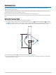
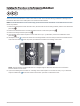
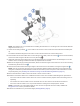
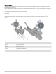
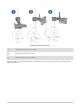
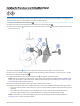
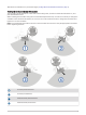
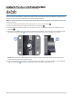
Table Of Contents
- Important Safety Information
- Tools Needed
- Mounting Considerations
- Installing the Transducer on the Perspective Mode Mount
- Installing the Transducer on a Trolling Motor Barrel
- Installing the Transducer on the Trolling Motor Shaft
- Installing the Transducer on a Pole
- Installing the Transducer Using Low Profile Mounting Hardware
- Mounting the GLS 10 Black Box Device
- Transducer Settings and Operation
- Specifications

NOTE: The rubber liner is not needed when installing the transducer on a trolling motor with a shaft diameter
larger than 25 mm (1 in.).
7 Orient the mounting bracket on the shaft so the arrows on the inside of the front half of the bracket point
up.
The bracket should be aligned so the center screw hole faces the front of the trolling motor.
8 Place bracket around the rubber liner on the trolling motor shaft, insert the screws into the mount bracket,
and secure them using the M5 hex wrench in parts bag .
9 (Optional) Transition the trolling motor from the deployed to the stowed position and back again to test the
location of the mounting bracket and make any adjustments as needed.
10 With the 90-degree angle pointing downward, attach the shorter length of the extension arm to the mounting
bracket using the shorter knob .
11 Place the transducer below the longer length of the extension arm and attach it using the longer knob .
NOTE: You can secure the extension arm to the mounting bracket and the transducer to the extension arm
using the included low-profile hardware instead of the knobs if you do not plan to switch transducer modes
frequently during use (Installing the Transducer Using Low Profile Mounting Hardware, page 14).
12 Secure the transducer cable to the motor shaft or other secure location.
13 Route the transducer cable to the installation location of the sonar module while taking these precautions.
• You must route the cable so that it does not come in contact with the propeller when the trolling motor is
operating.
• You should not route the cable close to electrical wires or other sources of electrical interference.
• You must route the cable so it is not pinched when the trolling motor is deployed or stowed.
NOTE: If necessary, for extra cable length you can connect an optional extension cable, available at
buy.garmin.com or from your Garmin dealer.
14 Position the transducer to your desired angle (Viewing Modes, page 6).
5