
Owner's Manual
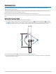
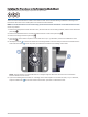
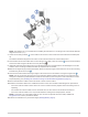
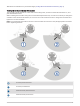
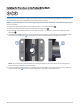
Table Of Contents
- Important Safety Information
- Tools Needed
- Mounting Considerations
- Installing the Transducer on the Perspective Mode Mount
- Installing the Transducer on a Trolling Motor Barrel
- Installing the Transducer on the Trolling Motor Shaft
- Installing the Transducer on a Pole
- Installing the Transducer Using Low Profile Mounting Hardware
- Mounting the GLS 10 Black Box Device
- Transducer Settings and Operation
- Specifications

Cable Considerations
NOTICE
Zip ties and cable clamps can over-tighten and damage or break the cable, or cause cable fatigue due to
repeated rotation of the motor.
You should use black electrical tape to secure the cable above and below the rotating joint. If you secure the
cable with zip ties, do not over-tighten the zip ties.
You should secure the cable above and below the pivot joint of your trolling motor.
You should create a service loop at least 25 cm (10 in.) long in the cable, with the rotating joint centered on the
loop.
Routing the Transducer Cable
You should test-fit the transducer and cable before installation.
1 Allow a loose gap of at least 10 cm ( 4 in.) above and 10 cm (4 in.) below the rotating joint to create a
loop in the cable. The loop must be large enough to allow full rotation of the transducer in both directions.
Allow a minimum of 25 cm (10 in.) of cable to cover the 20 cm (8 in.) section between mounting points.
2 Use black electrical tape to secure the transducer cable to the shaft.
3 Test the full rotation of the trolling motor to ensure the cable clears the rotating joint and is not pulled tight
due to tension during rotation.
3