
Owner's Manual
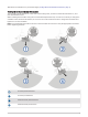
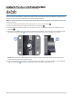
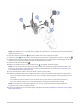
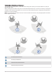
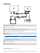
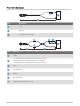
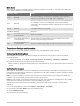
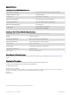
Table Of Contents
- Important Safety Information
- Tools Needed
- Mounting Considerations
- Installing the Transducer on the Perspective Mode Mount
- Installing the Transducer on a Trolling Motor Barrel
- Installing the Transducer on the Trolling Motor Shaft
- Installing the Transducer on a Pole
- Installing the Transducer Using Low Profile Mounting Hardware
- Mounting the GLS 10 Black Box Device
- Transducer Settings and Operation
- Specifications

Installing the Transducer Using Low Profile Mounting Hardware
If you do not plan to change the viewing mode of the transducer often, or prefer a lower-profile installation
without the adjustment knobs, you can use the included hardware to install the transducer instead of using the
knobs.
Labels identifying the parts bags required for this procedure:
1 Secure the mounting bracket to the trolling motor barrel (Installing the Transducer on a Trolling Motor Barrel,
page 8) or shaft (Installing the Transducer on the Trolling Motor Shaft, page 10) (Installing the Transducer on
the Perspective Mode Mount, page 4) according to the appropriate instructions, but do not use the included
adjustment knobs.
2 Select an action:
• If you are installing the transducer on the barrel or shaft of the trolling motor, use the longer low-profile
screw and metal washer from parts bag to secure the transducer to the mounting bracket.
• If you are installing the transducer using the perspective mode mount and extension arm, use the shorter
low-profile screw and metal washer from parts bag to secure the extension arm to the mounting
bracket, and use the longer low-profile screw and metal washer from parts bag to secure the
transducer to the extension arm.
3 Adjust the view of the transducer and tighten the low-profile screws using the M5 hex wrench in parts bag
.
Mounting the GLS 10 Black Box Device
NOTICE
If you are mounting the device in fiberglass, when drilling the pilot holes, use a countersink bit to drill a
clearance counterbore through only the top gel-coat layer. This will help to avoid cracking in the gel-coat layer
when the screws are tightened.
NOTE: Screws are included with the device, but they may not be suitable for the mounting surface.
Before you mount the device, you must select a mounting location, and determine what screws and other
mounting hardware are needed for the surface.
1 Place the black box device in the mounting location, and mark the location of the pilot holes.
2 Drill a pilot hole for one corner of the device.
3 Loosely fasten the device to the mounting surface with one corner, and examine the other three pilot-hole
marks.
4 Mark new pilot-hole locations if necessary, and remove the device from the mounting surface.
5 Drill the remaining pilot holes.
6 Secure the device to the mounting location.
14