
Owner's Manual
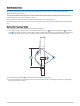
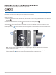
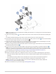
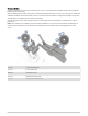
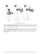
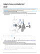
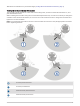
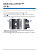
Table Of Contents
- Important Safety Information
- Tools Needed
- Mounting Considerations
- Installing the Transducer on the Perspective Mode Mount
- Installing the Transducer on a Trolling Motor Barrel
- Installing the Transducer on the Trolling Motor Shaft
- Installing the Transducer on a Pole
- Installing the Transducer Using Low Profile Mounting Hardware
- Mounting the GLS 10 Black Box Device
- Transducer Settings and Operation
- Specifications

Installing the Transducer on the Trolling Motor Shaft
Labels identifying the parts bags required for this procedure:
NOTICE
You must secure the transducer cable to the shaft or other secure location during installation. Damage to the
transducer cable wire or the cable jacket can cause transducer failure.
NOTE: To avoid obstructions in the sonar image, you should mount the transducer on the shaft as far from the
motor as possible.
1 Remove the back of the shaft-mount bracket and four screws from parts bag .
2 Remove the front half of the shaft mount bracket from parts bag .
3 If the trolling motor shaft is equal to or less than 25 mm (1 in.) in diameter, remove the rubber liner from
parts bag .
4 Identify the arrow on the front half of the shaft mount bracket to ensure that you orient the bracket with
the narrow end of the angle at the top when you attach the bracket to the trolling motor shaft.
NOTE: The trolling motor shaft bracket has an 8-degree angle to reduce the effects of the trolling motor
barrel interference with the transducer beam.
5 If you are installing the transducer on a trolling motor shaft equal to or less than 25 mm (1 in.) in diameter,
wrap the rubber liner around the shaft in the location you want to install the mount.
10