
Owner's Manual


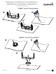

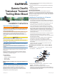
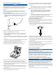
Table Of Contents
- STRIKER Vivid Owner’s Manual
- Table of Contents
- Introduction
- Customizing the Chartplotter
- ActiveCaptain® App
- Sonar Fishfinder
- Traditional Sonar View
- Garmin ClearVü Sonar View
- SideVü Sonar View
- Split-Screen Frequency
- Flasher
- Split-Zoom View
- Selecting the Transducer Type
- Sonar Frequencies
- Creating a Waypoint on the Sonar Screen Using the Device Keys
- Pausing the Sonar
- Adjusting the Zoom
- Sonar Gain
- Adjusting the Range of the Depth Scale
- Sonar Setup
- Garmin Quickdraw Contours Mapping
- Navigation with the STRIKER Vivid
- Searching for a Destination by Name
- Creating a Waypoint on the Map
- Navigating to a Waypoint
- Creating and Navigating a Route Using the Map
- Stopping Navigation
- Waypoints
- Routes
- Tracks
- Showing Tracks
- Clearing the Active Track
- Saving the Active Track
- Viewing a List of Saved Tracks
- Editing a Saved Track
- Saving a Track as a Route
- Browsing for and Navigating a Recorded Track
- Deleting a Saved Track
- Deleting All Saved Tracks
- Retracing the Active Track
- Setting the Color of the Active Track
- Managing the Track Log Memory During Recording
- Configuring the Recording Interval of the Track Log
- Device Configuration
- Sharing and Managing User Data
- Appendix
- Index
- STRIKER Vivid Quick Start Manual
- STRIKER™ Vivid 5/7/9 Fixed Bail Mount
- Garmin Clear Vü Transducer Transom/Trolling Motor Mount Installation Instructions
- Transducer Transom Mount Template
- Important Safety and Product Information

Installing the Transom-Mount Hardware
NOTICE
If you are mounting the bracket on fiberglass with screws, it is
recommended to use a countersink bit to drill a clearance
counterbore through only the top gel-coat layer. This will help to
avoid cracking in the gel-coat layer when the screws are
tightened.
The cables connected to the transducer should not be cut,
because cutting the transducer cables voids your warranty.
1
Cut out the template.
2
With the template
À
aligned vertically on the transom at the
installation location (Mounting Consideration, page 1), place
the bottom corner
Á
of the template on the edge of the
transom.
3
Mark the center location of the two holes of the template.
4
Remove the template from the transom.
5
Wrap a piece of tape around a 4 mm (
5
/
32
in.) bit at 18 mm
(
7
/
10
in.) from the point of the bit, to avoid drilling the pilot
holes too deep.
6
If you are installing the bracket on fiberglass, place a piece of
tape over the pilot-hole location to reduce cracking of the gel
coat.
7
Using the 4 mm (
5
/
32
in.) bit, drill the pilot holes approximately
18 mm (
7
/
10
in.) deep at the marked locations.
8
Apply marine sealant to the included 20 mm screws, and
attach the transducer assembly to the transom.
9
Route the cable under the transom mount cable hook.
10
If you must route the cable through the transom, choose a
pilot-hole location well above the waterline and mark it.
11
Place a cable clamp on the transducer cable, approximately
halfway between the transducer and the top of the transom or
the pass-through pilot hole.
12
Mark the pilot-hole location for the cable clamp, and using a
3.2 mm (
1
/
8
in.) bit, drill a pilot hole approximately 10 mm
(
3
/
8
in.) deep.
13
Apply marine sealant to the included 12 mm screw, and
attach the cable clamp to the transom.
14
If you marked a pilot hole in step 7, choose the appropriate
drill bit to drill a pass-through hole completely through the
transom:
• If you have the 4-pin cable, use a 16 mm (
5
/
8
in.) drill bit.
• If you have the 8-pin cable, use a 25 mm (1 in.) drill bit.
15
Route the transducer cable to the sounder:
• If you are routing the cable using a pass-through hole,
push it through the pass-through hole, and install the
cable-entry cover (Installing the Cable-Entry Cover,
page 2).
• If you are not routing the cable using a pass-through hole,
route the cable up and over the top of the transom.
You should avoid routing the cable close to electrical wires or
other sources of electrical interference.
Installing the Cable-Entry Cover
If you routed the cable through the transom after you installed
the transducer, you should install the cable-entry cover to keep
water from entering your boat.
1
Place the cable-entry cover
À
over the hole and the cable,
with the opening pointing downward, and mark the location of
the two pilot holes.
2
Remove the cable-entry cover, and, using a 3.2 mm (
1
/
8
in.)
bit, drill the pilot holes approximately 10 mm (
3
/
8
in.) deep.
3
Fill the pass-through hole with marine sealant so it covers the
cable completely and there is excess sealant around the hole
and the cable.
4
Place the cable-entry cover over the hole and the cable, with
the opening pointing downward.
5
Apply marine sealant to the included 12 mm M4 screws, and
attach the cable-entry cover to the transom.
6
Wipe away all excess marine sealant.
Testing the Installation
NOTICE
You should check your boat for leaks before you leave it in the
water for an extended period of time.
Because water is necessary to carry the sonar signal, the
transducer must be in the water to work properly. You cannot
get a depth or distance reading when out of the water. When
you place your boat in the water, check for leaks around any
screw holes that were added below the water line.
Testing the Transom-Mount Transducer Installation
NOTICE
When adjusting the depth of the transducer, make the
adjustments in small increments. Placing the transducer too
deep can adversely affect the performance of the boat and put
the transducer at risk of striking underwater objects.
Test the transom-mount transducer installation in open water
free of obstacles. Pay attention to your surroundings as you test
the transducer.
1
With the boat in the water, turn on the chartplotter.
2