
Owner's manual
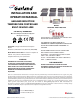

Installation RTCSmp Built-In Temperature Controlled Hold-Line
10 Part # 4532287 Rev 4 (6/10/14)
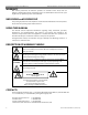
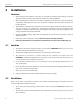
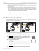
(G)
IMPORTANT Minimum clearance for air-exhaust outlets: 40mm / 1.57”
(H) IMPORTANT Minimum clearance for heat plate under counter surface: 100mm / 3.94”
(I) Cable for operation unit connecting to the induction generator, MAX 300cm / 118”.
(J) Cables for coil and sensors.
IMPORTANT Always route sensor and communication cables separately and away from the coil cables.
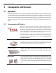
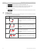
4.4 Configurations
One Induction Generator can power up to four (4) Heat Retaining Plates. You need to install two (2) control units
for any configurations with 2 to 4 Heat Retaining Plates.
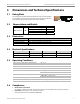
Model Configuration
(Heat Retaining Plate(s), Control Switch(s), and Induction Generator are shown)
HO IN 800
One switch controls one heat retaining plate.
One (1) heat retaining plate, one (1) generator and one (1)
control unit.
HO IN 1600
Two switches; each controls only one heat retaining plate.
Two (2) heat retaining plate, one (1) generator and two (2)
control units.
HO IN 2400
Two switches; one switch controls one heat retaining plate and
the other switch controls two plates.
Three (3) heat retaining plate, one (1) generator and two (2)
control units.
HO IN 3200
Two switches; each controls two heat retaining plates.
Four (4) heat retaining plate, one (1) generator and two (2)
control units.