
Manual

Installation RTCSmp Built-In Temperature Controlled Hold-Line
Part # 4532286 Rev 3 (6/10/14) 15
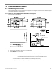
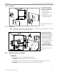
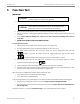
4.5.2.2 Front-Mount
To mount the control unit
onto the front of the panel:
1. Drill holes and make the
cut-out using the
dimensions and the actual
unit provided.
2. Secure the control unit to
the panel with fasteners.
Illustration: Measurements in mm
and [inch].
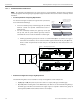
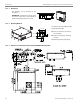
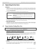
4.5.2.3 Back-Mount
NOTE For this type of installation, the maximum thickness of the panel must not exceed 3mm or 12 gauge.
This restriction ensures a proper grip on the knob.
To mount the control unit
from the back of the panel:
1. Drill holes on the panel using
the dimensions provided.
2. Remove the plastic knob
from the control unit and
attach the control unit to the
panel with fasteners as
shown. NOTE: DO NOT
remove or loosen any
screws on the control unit.
Illustration: Measurements in mm
and [inch].
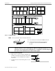
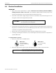
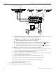
4.5.3 Induction Generator Installation
IMPORTANT
All connectors are located at the FRONT of the Generator.
CLEARANCE minimum 2.95”(75mm) in front of the connectors.
Ensure the generator and connectors can be accessed easily for electrical installation and service.
CLEARANCE minimum 1.57” (40mm) in front of the air-intake/exhaust outlets.
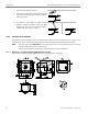
Front Panel
Front Panel
12 [ .474]
10.11 [ .398]
maximum
3 [0.12]