
Manual

Installation RTCSmp Built-In Temperature Controlled Hold-Line
Part # 4532286 Rev 3 (6/10/14) 13
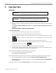
4.5.1.4 Installation Steps
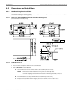
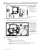
NOTE Please pay attention to the orientation of the unit.
A. The connectors are located at the FRONT of the unit
.
B. The digital temperature display underneath the
Ceran glass is located at the CENTER FRONT of
the unit.
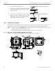
IMPORTANT To protect the induction unit from water penetration, you must apply and bond the silicone
adhesive properly to create a water-tight seal. Before you begin the installation, it is very
important to use isopropyl alcohol (minimum 70%) or equivalent to clean the flange and
the counter surfaces where the silicone adhesive will be applied.
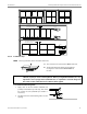
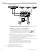
To install the Heat Retaining Plate:
1. Apply dots of silicone adhesive PACTAN (not
provide) all around the top of the step. This allows
for leveling the unit. (PACTAN part number =
70000015.)
2. Carefully lower the Heat Retaining Plate into the
opening.
A
B
C D
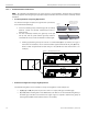
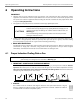
minimum 75.0mm / 2.95”
gap between Heat Plates
from dierent units
Unit 1
Unit 2
minimum 75.0mm / 2.95”
gap between Heat Plates
from dierent units
Unit 1
Unit 2
E
F
A
B