
User guide

Installation RTCSmp Built-In Temperature Controlled Hold-Line
Part # 4532288 Rev 3 (6/11/14) 13
4.4.4 Installation Steps
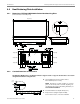
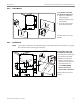
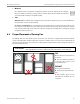
NOTE
Please pay attention to the orientation of the unit.
The digital displays underneath the Ceran glass are on the
opposite side of the RJ45 plug connectors.
For a typical installation, the controls should be installed
on the same side as the digital displays (Front). For parallel
installation (see section 4.4.3), the controls are to be
installed on the Left/Right side of the units.
IMPORTANT To protect the induction unit from water penetration, you must apply and bond the silicone
adhesive properly to create a water-tight seal. Before you begin the installation, it is very
important to use isopropyl alcohol (minimum 70%) or equivalent to clean the flange and
the counter surfaces where the silicone adhesive will be applied.
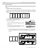
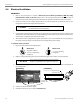
To install the Heat Retaining Plate:
1. Apply dots of silicone adhesive PACTAN (not
provide) all around the top of the step. This allows
for leveling the unit. (PACTAN part number =
70000015.)
2. Carefully lower the Heat Retaining Plate into the
opening.
3. Center the unit within the cut-out.
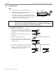
4. Level and press the flange into the silicone at the
same time. Ensure both the countertop and the
hob(s) are leveled.
5. To provide a water tight seal, apply silicone
adhesive completely around, filling any gaps
between the unit and the counter-top surface.
Carefully wipe up the excess silicone.
FRONT:
Digital Displays
under Glass-Top
Plugs for
Control Units
SIDE
(Left/Right)