
Owner's manual
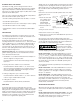
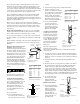

3. Attach the other end of the RV5 to the 5 Ib. cylinder valve by
plugging it into the quick coupling (Refer to Figure 17).
4. Chill the 5 Ib. cylinder as follows:
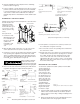
(a) With the valve on the 5 Ib. cylinder in the open position
(handle depressed), open the 50 Ib. cylinder rotary valve
for a full six seconds.
(b) Close both valves.
(c) Release trapped pressure in the RV5 by loosening the
coupling nut at the 50 Ib. cylinder valve.
(d) Remove the RV5 from the 50 Ib. cylinder valve.
(e) With the RV5 still attached to the 5 Ib. cylinder, hold the
hose and point it in a safe direction. Operate the 5 Ib.
cylinder valve and release a short burst (3 to 4 seconds)
of CO
2
. Expelling CO
2
from the 5 Ib. cylinder will cause it
to become chilled.
5. Re-attach the RV5 to the 50 Ib. cylinder.
6. Open both cylinder valves and fill the 5 Ib. cylinder.
7. Close both valves when the audible sound of CO
2
flow stops
(about 15-30 seconds).
8. Disconnect the RV5 coupling nut from the 50 Ib. cylinder
valve first. This will bleed the trapped pressure in the hose
and prevent damage to the O-ring in the 5 Ib. cylinder oper-
ating valve.
9. Weigh the 5 Ib. cylinder. A full cylinder should weigh the total
obtained by adding 5 Ibs. to the empty weight.
10. If the 5 Ib. cylinder is underweight, operate the valve as in
step 4 and re-chill the cylinder. Re-attach the RV5 to both
50 Ib. and 5 Ib. cylinders and repeat steps 5, 6, 7, and 8.
11. If overweight, leave cylinder on the scales and bleed CO
2
until the correct weight is obtained.
NOTE: After the 5 Ib. cylinder has been filled, it may be very cold,
and the pressure may be low. It is recommended that the
cylinder be stored overnight at room temperature (70°F.).
This will insure full working capability of the cylinder.
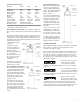
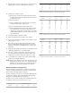
MAXIMUM NUMBER OF CONDUIT RUNS
The following tables are presented as a guide to the maximum
number of conduit runs that can be achieved in “sealed” conduit
before refilling of the CO
2
cylinder is required.
“Sealed” conduit for this purpose is considered as EMT with com-
pression type couplings, rigid conduit with threaded couplings
and plastic conduit with adhesive bonded joints.
Conditions of the conduit, operating valve adjustment and opera-
tor experience will cause the number of runs to vary.
Conduit Conduit Run Length (feet)
Diameter 100’ 200’ 300’ 400’
1
/
2
” 170 80 55 40
3
/
4
”75352017
1” 42 20 13 10
1
1
/
4
”281286
1
1
/
2
”18864
2” 14 5 3 2
2
1
/
2
”7320
Table 3
5 Ib. CO
2
Cylinder Maximum Number of Conduit Runs Before Refilling
Conduit Conduit Run Length (feet)
Diameter 100’ 200’ 300’ 400’
1
/
2
” 700 345 225 170
3
/
4
” 315 155 103 79
1” 175 86 58 42
1
1
/
4
” 115 57 38 28
1
1
/
2
”78382518
2” 44 21 14 10
2
1
/
2
”281497
3” 19 9 6 4
3
1
/
2
”14743
4” 11 5 3 2
5” 7 3 2
6” 4 2
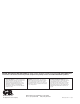
Table 4
20 Ib. CO
2
Cylinder Maximum Number of Conduit Runs Before Refilling
Conduit Conduit Run Length (feet)
Diameter 100’ 200’ 300’ 400’
1
/
2
” 1750 876 582 439
3
/
4
” 796 396 260 196
1 ” 443 220 145 107
1
1
/
4
” 290 142 95 70
1
1
/
2
” 195 96 64 47
2” 108 52 35 26
2
1
/
2
”64322116
3” 44 22 14 11
3
1
/
2
”3316108
4” 25 12 8 6
5” 16 8 5 4
6” 11 5 3 2
Table 5
50 Ib. CO2 Cylinder Maximum Number of Conduit Runs Before Refilling.
7