
Manual

10
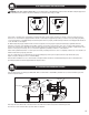
17.0 OFFSET BENDING INFORMATION AND CHARTS
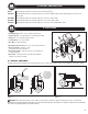
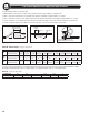
To locate bending marks for a desired offset:
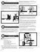
1. Measure distance from end of conduit to start of bend and mark conduit. ( Mark 1 ) See Figure 19b.
2. Refer to chart E for measurement “X” and deduct this distance from Mark 1 and place Mark 2 on conduit.
3. Refer to chart D for center-to-center distance between marks. Measure this distance from Mark 2 and place Mark 3 on conduit.
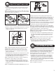
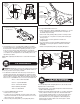
4. Layout of bends is now complete. Next, place Mark 2 in line with front edge of shoe hook and make first bend. See Figure 19c.
5. Rotate conduit 180 degrees. Place Mark 3 in line with front edge of shoe hook and complete second bend.
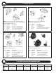
To locate center-to-center distance of offset bending marks other than those listed in Chart D, use the following multipliers. Multiply
the height of offset desired by 3.86 on 15 degree bends, 2 on 30 degree bends, and 1.4 on 45 degree bends.
Angle
Figure 19a
Offset
Height
End of Conduit
to Start of Bend
Center to Center
Length
Mark No. 3
Deduct
Length
Mark No. 1
Figure 19b
Place Bending Mark in Line
with Front Edge of Shoe Hook
Figure 19c
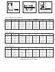
Offset Height 2 4 6 8 10 12 14 16 18 20 22
15°
Max Conduit Size 3/4" 1-1/2" 2" 2" and smaller
Center-to-Center 7-3/4" 15-7/16" 23-3/16" 30-15/16" 38-5/8" 46-3/8" 54-1/16" 61-13/16" 69-9/16" 77-1/4" 85"
30°
Max Conduit Size 3/4" 1" 1-1/2" 2" 2" and smaller
Center-to-Center 8" 12" 16" 20" 24" 28" 32" 36" 40" 44"
45°
Max Conduit Size 1/2" 1" 1-1/4" 1-1/2" 2" 2" and smaller
Center-to-Center 8-1/2" 11-5/16" 14-1/8" 16-15/16" 19-13/16" 22-5/8" 25-7/16" 28-1/4" 31-1/8"
Chart D – Offset Height Figures are approximate.
Conduit Size
1/2 3/4 1 1-1/4 1-1/2 2
"X"
3-1/16" 3-1/16" 3-1/16" 4" 4-1/4" 4-1/2"
Chart E Figures are approximate.