
Manual


5
7. Use the control pendant. The zero light should be
on. Hold the toggle switch in the “Bend” position.
The shoe will rotate until the desired bend is
achieved, then stop automatically.
NOTE: If the zero light is not on, press the toggle
switch to return until the shoe stops and the zero
light comes on.
8. To unload conduit, hold the toggle switch in the
“Return” position. The shoe will return to the start
position and stop automatically.
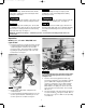
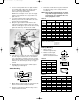
9. Grasp the upper urethane roller and move the
support arm clockwise until the rollers move away
from the conduit (figure 10). Push the roller housing
against the frame stop. Remove bent conduit.
10. To bend more conduit of the same material and at
the same angle, load and secure as described in
steps 3 through 6. To bend the same type conduit
but at a different angle, load and secure; turn angle
indicator to the desired angle, then press toggle
to bend.
11. Bending different type and size conduit requires
repeating steps 2 through 10.
Offset Conduit Conduit Conduit
Required Max. Size M Max. Size M Max. Size M
2”
3
⁄
4
”7
3
⁄
4
”
4” 1
1
⁄
2
”15
7
⁄
16
”
3
⁄
4
”8”
6” 2” 23
3
⁄
16
” 1” 12”
1
⁄
2
”8
1
⁄
2
”
8” 30
5
⁄
8
”1
1
⁄
2
” 16” 1” 11
5
⁄
16
”
10” 38
5
⁄
8
” 2” 20” 1
1
⁄
4
”14
1
⁄
8
”
12” 46
3
⁄
8
” 24” 1
1
⁄
2
”16
15
⁄
16
”
14” 54
1
⁄
16
” 28” 2” 19
13
⁄
16
”
16” 61
13
⁄
16
” 32” 22
5
⁄
8
”
18” 67
7
⁄
16
” 36” 25
7
⁄
16
”
20” 77
1
⁄
4
” 40” 28
1
⁄
4
”
22” 85” 44” 31
1
⁄
8
”
To locate distance between centers of offset bending marks other than listed in
table A use the following multipliers:
15˚ bend - 3.9
30˚ bend - 2.0
45˚ bend - 1.4
Table A
15˚ Bend 30˚ Bend 45˚ Bend
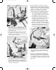
1. Obtain distance “M" from table A, and measure this
distance from mark #1 and place mark #2.
2. Now place mark #1 in line with front edge of shoe
clamp and make first bend.
Offset
Beam
Box
M
Front Edge of Clamp
See Table A
Min. 2"
Mark #2Mark #1
Offset Bending
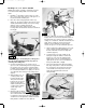
Stub-up Bending
Shoe
Min. 2˝
Stub Length
Set Back
Mark #2
Mark #1
Front Edge of
Clamp Mark #2
Stub to Bottom
of Pipe
1. Table C shows
minimum length (inches).
2. Mark #1 is stub length,
deduct from this as per
table C and obtain mark #2.
3. Next rotate conduit 180˚ level, place mark #2 in
line with front edge of shoe clamp and make
second bend.
NOTE: When bending rigid aluminum, set bend
angle indicator approximately 4˚ short of
desired angle, since aluminum does not
have spring-back of steel.
1
⁄
2
” Rigid 7
3
⁄
4
”1
1
⁄
4
” Rigid 12
3
⁄
4
”
1
⁄
2
” IMC 7
3
⁄
4
”1
1
⁄
4
” IMC 12
1
⁄
2
”
1
⁄
2
” EMT 7
5
⁄
8
”1
1
⁄
4
” EMT 13”
3
⁄
4
” Rigid 9” 1
1
⁄
2
” Rigid 13
1
⁄
2
”
3
⁄
4
” IMC 9” 1
1
⁄
2
” IMC 13
1
⁄
2
”
3
⁄
4
” EMT 8
1
⁄
2
”1
1
⁄
2
” EMT 13
1
⁄
2
”
1” Rigid 10
1
⁄
8
” 2” Rigid 15
3
⁄
4
”
1” IMC 10
1
⁄
8
” 2” IMC 15
1
⁄
2
”
1” EMT 10
3
⁄
8
” 2” EMT 15
1
⁄
2
”
Table C
Conduit Stub-up Conduit Stub-up
Size Set-back Size Set-back
Conduit Radius Radius
Size Rigid / IMC EMT
1
⁄
2
”3
31
⁄
32
”3
7
⁄
8
”
3
⁄
4
”4
25
⁄
32
”4
29
⁄
32
”
1” 5
9
⁄
16
”5
29
⁄
32
”
1
1
⁄
4
”6
7
⁄
8
”7
3
⁄
32
”
1
1
⁄
2
”7
9
⁄
16
”7
1
⁄
2
”
2” 8
9
⁄
32
”8
9
⁄
16
”
Table B
BEND RADIUS
Figure 10
Roller Housing Handle
Upper
Urethane Roller
Frame Stop
RPS-0097 3/27/00 1:03 PM Page 5