
Installation Instructions

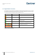
Table Of Contents
- 1 INTRODUCTION
- 2 GENERAL INFORMATION
- 3 INSTALLATION
- 3.1 Target Group
- 3.2 Definition of the Door Hinge (Right of Left Door)
- 3.3 Test Installation
- 3.4 Metallic and Non-Metallic Doors
- 3.5 Bolt Gauge
- 3.6 Door Status Contact
- 3.7 Transportation Guidelines
- 3.8 Replacement after a Burglary Attempt
- 3.9 Measurement Diagrams for Installation
- 3.10 Installation in Lockers with Non-Metallic Doors (Except Glass)
- 3.11 Installation in Lockers with Metallic Doors
- 3.12 Installation in Lockers with Glass Doors
- 4 COMMISSIONING
- 5 CONFIGURATION
- 5.1 General Information
- 5.2 Setup for Configuration in GAT Config Manager
- 5.3 View and Edit the GAT ECO.Side Lock 7000 BA Configuration Settings
- 5.4 Upload Configuration Settings to the GAT ECO.Side Lock 7000 BA
- 5.5 Updating the GAT ECO.Side Lock 7000 BA Firmware
- 5.6 Configuration Settings of the GAT ECO.Side Lock 7000 BA
- 6 OPERATION
- 7 CLEANING AND MAINTENANCE
- 8 TECHNICAL DATA

GAT ECO.Side Lock 7000 BA / NW BA
Operation
58
HB_GAT-GAT-ECOSide-Lock7000-BA--EN_14
www.gantner.com
6.7 Signalization Overview
The electronics in the GAT ECO.Side Lock 7000 BA are activated by pushing the locker door shut, i.e., when the
door shackle is fully inserted into the opening of the lock. This activation is signaled by the LED flashing orange
once. Directly thereafter the following lock states are signaled by the LED.
LED Color
Signalization
Meaning
1 x orange flash
- Lock ready to read a data carrier
1 x red flash
- No authorization
- Error
1 x green flash
- Data carrier accepted
- Operation successful
- 1 x green flash
- Beeps ascending in pitch
- Battery replacement successfully completed
- Lock operating in the normal operating mode again
Flashing red/green
- Lock is in configuration mode
- Lock waiting to read a data carrier
- 5 x red flashes
- 5 x beeps
- Battery change required
Table 6.2 - Overview of the signalization