
Installation Instructions

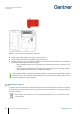
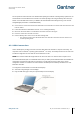
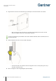
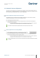

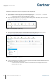
Table Of Contents
- 1 INTRODUCTION
- 2 GENERAL INFORMATION
- 3 INSTALLATION
- 3.1 Target Group
- 3.2 Definition of the Door Hinge (Right of Left Door)
- 3.3 Test Installation
- 3.4 Metallic and Non-Metallic Doors
- 3.5 Bolt Gauge
- 3.6 Door Status Contact
- 3.7 Transportation Guidelines
- 3.8 Replacement after a Burglary Attempt
- 3.9 Measurement Diagrams for Installation
- 3.10 Installation in Lockers with Non-Metallic Doors (Except Glass)
- 3.11 Installation in Lockers with Metallic Doors
- 3.12 Installation in Lockers with Glass Doors
- 4 COMMISSIONING
- 5 CONFIGURATION
- 5.1 General Information
- 5.2 Setup for Configuration in GAT Config Manager
- 5.3 View and Edit the GAT ECO.Side Lock 7000 BA Configuration Settings
- 5.4 Upload Configuration Settings to the GAT ECO.Side Lock 7000 BA
- 5.5 Updating the GAT ECO.Side Lock 7000 BA Firmware
- 5.6 Configuration Settings of the GAT ECO.Side Lock 7000 BA
- 6 OPERATION
- 7 CLEANING AND MAINTENANCE
- 8 TECHNICAL DATA

GAT ECO.Side Lock 7000 BA / NW BA
Commissioning
36
HB_GAT-GAT-ECOSide-Lock7000-BA--EN_14
www.gantner.com
► Plug the Micro-B connector of the USB cable into the USB port on the GAT ECO.Side Lock 7000 BA.
o After connecting the GAT ECO.Side Lock 7000 BA to the PC/laptop for the first time, the lock
drivers are installed, and the lock is automatically recognized.
If a driver is requested, they are available on the “Leisure Software” USB stick, which is included in the GAT
ECO.Basic Set B BA.
► Hold the SERVICE data carrier next to the RFID reading field.
o The GAT ECO.Side Lock 7000 BA enters into configuration mode. The LED pulses green every 2
seconds to indicate this state.
► Click on “Configure” in GAT Config Manager to open the settings.