
Installation Instructions
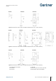
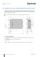
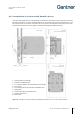
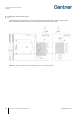
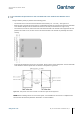
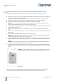
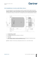
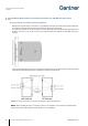
Table Of Contents
- 1 INTRODUCTION
- 2 GENERAL INFORMATION
- 3 INSTALLATION
- 3.1 Target Group
- 3.2 Definition of the Door Hinge (Right of Left Door)
- 3.3 Test Installation
- 3.4 Metallic and Non-Metallic Doors
- 3.5 Bolt Gauge
- 3.6 Door Status Contact
- 3.7 Transportation Guidelines
- 3.8 Replacement after a Burglary Attempt
- 3.9 Measurement Diagrams for Installation
- 3.10 Installation in Lockers with Non-Metallic Doors (Except Glass)
- 3.11 Installation in Lockers with Metallic Doors
- 3.12 Installation in Lockers with Glass Doors
- 4 COMMISSIONING
- 5 CONFIGURATION
- 5.1 General Information
- 5.2 Setup for Configuration in GAT Config Manager
- 5.3 View and Edit the GAT ECO.Side Lock 7000 BA Configuration Settings
- 5.4 Upload Configuration Settings to the GAT ECO.Side Lock 7000 BA
- 5.5 Updating the GAT ECO.Side Lock 7000 BA Firmware
- 5.6 Configuration Settings of the GAT ECO.Side Lock 7000 BA
- 6 OPERATION
- 7 CLEANING AND MAINTENANCE
- 8 TECHNICAL DATA

GAT ECO.Side Lock 7000 BA / NW BA
Installation
www.gantner.com
HB_GAT-GAT-ECOSide-Lock7000-BA--EN_14
21
Figure 3.6 - Dimensions of the GAT NET.Lock BoltSet 7100 (dimensions in mm – inches in brackets)
Figure 3.7 - Dimensions of the GAT NET.Lock BoltSet 7200 (dimensions in mm – inches in brackets)
Figure 3.8 - Dimensions of the GAT NET.Lock BoltSet 7300 (dimensions in mm – inches in brackets)
1. GAT ECO.Side Lock 7000 BA
4. Status LED
2. Door shackle
5. Label carrier (front cover on door outer side)
3. Door contact
6. Metal support for glass door installation