
User's Manual
Galaxy Tracking Systems, L.L.C. VTU User’s Guide
10
Use or disclosure of data contained on this sheet is subject to the restriction on the title page of this report.
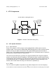
on the Switch Box for each of the three inputs. When pressed, two of the switches
issue silent alarms (SOS, Assistance) and the third toggles the unauthorized movement
sensor between the armed and disarmed states. The remaining input is used to sense
activation of the vehicle alarm system (if present).
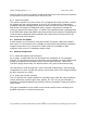
7.2 Outputs
Each of the three Switch Box switches have an associated status LED output (pins 5-7
on J1). When one of the silent alarm switches is pressed, the corresponding LED will
flash at a 1 Hz rate to indicate an alarm has been sent to the command center. When
the alarm is acknowledged, the LED lights continuously. The LED can only be
extinguished (and the alarm cleared) from the command center. The third LED is lit
when the unauthorized movement sensor is armed.
The fourth output (pin 8) drives an LED that indicates VTU power and blinks off
whenever the VTU transmits.
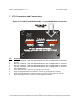
The remaining four outputs (pins 4, 5, 6 and 7) can drive small loads (<20mA) and must
be interfaced to real world circuits through high current drivers (MOSFETS) or relays.
These outputs are dedicated to the control of external devices such as vehicle
accessories, horns, etc.
7.3 Power
7.4 Antennas