
User's Manual


Galaxy Tracking Systems, L.L.C. VTU User’s Guide
9
Use or disclosure of data contained on this sheet is subject to the restriction on the title page of this report.
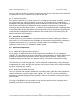
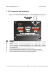
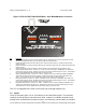
Figure 5 VTU OUTPUT PIN DEFINITIONS - 8 pin BROWN Molex Connector
Pin Function
1 Power / Transmit LED (Connect anode of LED to this pin, cathode to pin 9 of the 10 pin Molex or other
ground point) Illuminates when unit is powered, blinks off during transmit.
2 Unauthorized Movement Indicator LED (Connect cathode of LED to this pin, anode through 500 ohm
resistor to 12V)
3 Roadside Assistance request Indicator LED (Connect cathode of LED to this pin, anode through 500 ohm
resistor to 12V)
4 SOS Indicator LED (Connect cathode of LED to this pin, anode through 500 ohm resistor to 12V)
5 Engine Disable Relay control—Inactive: 0V. Active: 5V to shut off engine. WARNING, This output can
only provide 20 ma of current. Drawing more than 20 ma at this pin will destroy the device. There MUST
be a current amplification device at this output to drive the relay.
6 Signal Light Relay control—Inactive: 0V. Active: oscillates to 0 to 5V to flash signal lights. WARNING,
This output can only provide 20 ma of current. Drawing more than 20 ma at this pin will destroy the
device. There MUST be a current amplification device at this output to drive the relay.
7 Horn Relay control—Inactive: 0V. Active: oscillates 0 to 5V to honk horn. WARNING, This output can
only provide 20 ma of current. Drawing more than 20 ma at this pin will destroy the device. There MUST
be a current amplification device at this output to drive the relay.
8 Headlights Relay control—Inactive: 0V. Active: oscillates 0 to 5V to flash headlights. WARNING, This
output can only provide 20 ma of current. Drawing more than 20 ma at this pin will destroy the device.
There MUST be a current amplification device at this output to drive the relay.
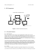
The VTU is equipped with a total of four inputs (J2) and eight outputs (J1).
7.1 Inputs
Three of the inputs (pins 1-3 on J2) interface to the Switch Box option. The functions
currently served by these connections are SOS, request for roadside assistance and
arming of the unauthorized movement sensor. A momentary contact switch is provided