
User's Manual

Galaxy Tracking Systems, L.L.C. VTU User’s Guide
8
Use or disclosure of data contained on this sheet is subject to the restriction on the title page of this report.
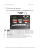
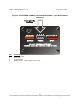
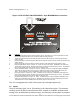
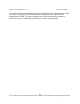
Figure 4 VTU POWER CONNECTOR PIN DEFINITIONS - 4 pin WHITE Molex
Connector
Pin Function
1 Chassis Ground
2 VCC +12V
3 No Connection
4 Ignition Sense-- +12V if engine on/ 0 V if off