
Service Manual


SECTION 6
6-1
Part No. 001-3474-002
ALIGNMENT PROCEDURE AND PERFORMANCE TESTS
6.1 GENERAL
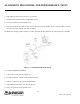
Receiver or transmitter alignment may be necessary if repairs are made that could affect tuning. Alignment
points diagrams are located in Figure 6-3 or component layouts are located in Section 8.
Fabricate test cables by referring to Section 2.2, Interfacing with Data Equipment. This cable should include
power and ground, a transmit keying switch that shorts the keying line to ground, data input and data output. The
test setup must apply the various supply voltages and load the synthesizer with channel information.
6.2 DL3474 TRANSCEIVER ONLY
6.2.1 FREQUENCY AND CONTROL LINE VOLTAGE CHECK
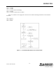
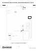
1. Connect the test setup shown in Figure 6-1. Set the power supply for +7.5V DC.
2. Load the synthesizer with the channel frequency (see Section 3.2).
3. Connect a DC voltmeter at the junction of R808/C815 to measure the VCO control line voltage for a meter
reading of ≥0.50 - ≤4.90V DC (see Figure 6-3).
4. Key the transmitter.
5. Measure the VCO control line voltage for a meter reading of ≥0.75 - ≤5.00V DC
6. Unkey the transmitter.
6.2.2 2W TRANSMITTER POWER ALIGNMENT
1. Connect the test setup shown in Figure 6-1. A DC ammeter capable of measuring up to 1.5A should be installed
in the supply line.
2. Load the synthesizer with the center channel frequency.
3. Key the transmitter and make sure that the supply voltage at the RF board is 7.5V.
(Do not transmit for extended periods.)
4. Adjust C553 counterclockwise for minimum current.
5. Connect a voltmeter to the junction of R542/R543.