
Service Manual

CIRCUIT DESCRIPTION
4-2
Part No. 001-3474-002
4.1.4 TRANSMITTER
The transmitter produces a nominal RF power output of 2W adjustable to 500 mW (-XX0). Frequency
modulation of the transmit signal occurs in the synthesizer. Transmit audio processing circuitry is contained in the
customer-supplied equipment.
4.2 SYNTHESIZER
4.2.1 INTRODUCTION
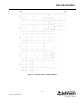
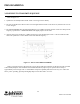
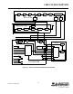
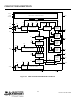
A block diagram of the synthesizer is shown in Figure 4-1 and a block diagram of Synthesizer IC U801 is
shown in Figure 4-2. As stated previously, the synthesizer output signal is produced by a VCO (voltage controlled
oscillator). The VCO frequency is controlled by a DC voltage produced by the phase detector in U801. The phase
detector senses the phase and frequency of the two input signals and causes the VCO control voltage to increase or
decrease if they are not the same. The VCO is then “locked” on frequency.
Programming of the synthesizer provides the data necessary for the internal prescaler and counters. One input
signal is the reference frequency. This frequency is produced by the 17.5 MHz reference oscillator (TCXO). The
other input signal is the VCO frequency.