
User's Manual
Galaxy Tracking Systems, L.L.C. Technical Documentation - VTU
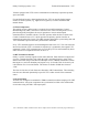
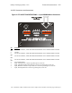
embedded controller equipped with a Motorola M68HC11E1 microcontroller, 32
Kilobytes of flash ROM, 32 Kilobytes of SRAM and various support components to
enable the circuitry to perform the desired tasks. In addition, the baseband board is
equipped with a MX-COM 909A single chip GMSK data pump modem for the purpose
of providing the communications subsystem with modulation and Forward Error
Correction (FEC) for data transmission and reception.
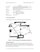
6.2 Antennas and Cables
A GPS Antenna, a UHF antenna, associated cables and power cabling are included with
each VTU. GPS antennas are available as permanently mounted units, temporary
magnetic mount units or as covert units. Similar options are available for UHF antennas.
Refer to the VTU Installation Guide details.
6.3 Optional Components
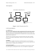
6.3.1 Switch Box (Alarms and Indicators)
As an option, a small switch box can be acquired for installation in VTU equipped
vehicles. The box houses the three momentary contact switches for issuing alarms and
arming the unauthorized movement sensor and four LED indicators. Three of the
indicators display alarm status, the fourth monitors VTU power and transmit activity.
The switch box is small enough that it can be mounted unobtrusively in the passenger
compartment in such a way that the operator can monitor status, but it will go unnoticed
by other occupants (or a thief).
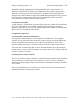
6.3.2 Relay Box (Vehicle Controls)
The VTU provide four outputs suitable for controlling relays. With the relays installed in
various automotive systems, lights, horn, ignition, etc. the VTU can be controlled or
disabled by suitably equipped chase vehicles. Refer to the Mobile Tracking Unit (MTU)
User’s Guide.
This type of installation is very model or even vehicle specific and is ordinarily left to
qualified mechanics or motor pool personnel.
Use or disclosure of data contained on this sheet is subject to the restriction on the title page of this report.