
User's Manual

Galaxy Tracking Systems, L.L.C. Technical Documentation - VTU
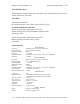
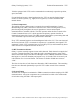
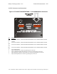
VTU Components
GPS S ubsys tem
(GPS Receiver)
Di gital B ase ba nd
Subsyst em
(Micro Controller)
p,v,t
ID, stat us
Communications
Subsyst em
(Radio Modem)
Packets ,
Tim ing data /
control
Feat ures
3 Fr eq b etw ee n (450-470 Mhz)
9600 ba ud GMSK mod ulati on
Forward Error Correction (Hamming code, Data Interleaving)
2 watt transmi t pow er
20 K r an ge
GPS
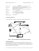
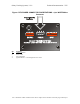
VLaTS Vehicle Tracking Unit (VTU)
p,v,t, ID,st atus
Com mands,
Timing
Stat us I ncl u des:
H ardwar e st at us
GPS Tr acki ng s tat us
Discretes st atus
Config ur ati on,
Initializ ation,
GPS Corr ecti ons
Vehicl e
Movement,
SOS,
Assistanc e,
Car Alarm
Unaut hor iz ed M ov ement
Armed,
SOS,
Assistanc e
Discretes
Indic ators
UHF
Figure 2 - Vehicle Transceiver Unit (VTU)
6.1 VTU System Enclosure
6.1.1 GPS Receiver
Every VTU contains a GPS receiver and is equipped with a GPS antenna and an antenna
cable. The receiver is differentially aided through the RF link to provide vehicle position
accuracy to within a few meters and synchronized system time accurate to within .5 ms.
The position information is transmitted to the command center at a precise predetermined
moment based on system time.
The GPS receiver will report a position at 0 degrees latitude and 0 degrees longitude
unless it can find and track GPS satellites. This takes less than a minute under normal
circumstances.
6.1.2 Radio
The VTU radio is capable of operation on 16 distinct frequencies over the frequency
range of 150 to 174 MHz at 2 watts. Frequencies are preset at the factory and selected for
operation from the command center via the RF link.
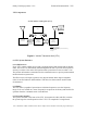
6.1.3 System Controller
The system controller is the heart of the VTU. It integrates the radio and GPS, contains
the system logic the overall operation of the VTU. It is comprised of a single board
Use or disclosure of data contained on this sheet is subject to the restriction on the title page of this report.