
User's Manual

Galaxy Tracking Systems, L.L.C. Technical Documentation - VTU
Options
Input Switch Box: Connects to V-Trak™, Provides driver with Panic Button / assistance
request functions; alternatively used for status indications
Output Relays: High current relays allow V-Trak™ outputs to be used to control vehicle:
engine kill, unlock door, honk horn, etc.
Antennas: Magnetic mount, permanent mount, and hidden GPS and VHF antennas
Backup Battery: 4 hour or 16 hour operation
Power Requirements:
Voltage: 12 VDC nominal
Current Draw: 250 mA at idle, 1.1 amp while transmitting
Physical / Environmental
Dimensions: 16.5 cm x 10 cm x 5 cm
Operating temperature: -30°C to +60°C
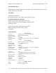
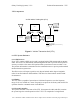
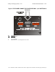
5.0 SYSTEM OVERVIEW
A typical configuration of Galaxy’s vehicle tracking system is illustrated below.
CENTRAL
COMMAND
CENTER
(CCC)
CENTRAL
COMMAND
CENTER
(CCC)
CENTRAL BROADCASTING
UNIT (CBU)
GPS SATELLITE NETWORK
FIXED TRACKING
UNIT (FTU)
FTU
FTU
DIGITAL DATA
LINK (DDL)
DDL
DDL
DDL
Private Vehicle
Transceiver Unit
(VTU)
Mobile
Tracking
unit
(MTU)
RF
RF
RF
RF
RF
Fleet Vehicle
Tranceiver Unit
(VTU)
GPS
GPS
RF
Figure 1 - Vehicle Location and Tracking System Architecture
5.1 Mobile Components
The Vehicle Transceiver Unit (VTU) is the mobile component of Galaxy’s vehicle
location and tracking system. Each VTU contains a GPS receiver to determine location,
and a VHF radio for communications. VTUs run directly off of vehicular battery power
and are small enough to be easily hidden.
Use or disclosure of data contained on this sheet is subject to the restriction on the title page of this report.