
User's Manual

Galaxy Tracking Systems, L.L.C. Technical Documentation - VTU
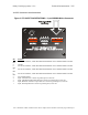
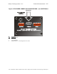
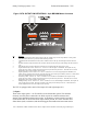
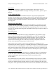
Figure 5 VTU OUTPUT PIN DEFINITIONS - 8 pin BROWN Molex Connector
Pin Function
1 Power / Transmit LED (Connect anode of LED to this pin, cathode to pin 9 of the 10 pin Molex or other ground
point) Illuminates when unit is powered, blinks off during transmit.
2 Unauthorized Movement Indicator LED (Connect cathode of LED to this pin, anode through 500 ohm resistor to
12V)
3 Roadside Assistance request Indicator LED (Connect cathode of LED to this pin, anode through 500 ohm resistor to
12V)
4 SOS Indicator LED (Connect cathode of LED to this pin, anode through 500 ohm resistor to 12V)
5 Engine Disable Relay control—Inactive: 0V. Active: 5V to shut off engine. WARNING, This output can only
provide 20 ma of current. Drawing more than 20 ma at this pin will destroy the device. There MUST be a current
amplification device at this output to drive the relay.
6 Signal Light Relay control—Inactive: 0V. Active: oscillates to 0 to 5V to flash signal lights. WARNING, This
output can only provide 20 ma of current. Drawing more than 20 ma at this pin will destroy the device. There MUST
be a current amplification device at this output to drive the relay.
7 Horn Relay control—Inactive: 0V. Active: oscillates 0 to 5V to honk horn. WARNING, This output can only
provide 20 ma of current. Drawing more than 20 ma at this pin will destroy the device. There MUST be a current
amplification device at this output to drive the relay.
8 Headlights Relay control—Inactive: 0V. Active: oscillates 0 to 5V to flash headlights. WARNING, This output can
only provide 20 ma of current. Drawing more than 20 ma at this pin will destroy the device. There MUST be a
current amplification device at this output to drive the relay.
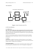
The VTU is equipped with a total of four inputs (J2) and eight outputs (J1).
7.1 Inputs
Three of the inputs (pins 1-3 on J2) interface to the Switch Box option. The functions
currently served by these connections are SOS, request for roadside assistance and
arming of the unauthorized movement sensor. A momentary contact switch is provided
on the Switch Box for each of the three inputs. When pressed, two of the switches issue
silent alarms (SOS, Assistance) and the third toggles the unauthorized movement sensor
Use or disclosure of data contained on this sheet is subject to the restriction on the title page of this report.