Vehicle Location and Tracking System (VLaTS) Vehicle Transceiver Unit (VTU) User’s Guide 7 Sept 1999 Prepared By: Galaxy Scientific Corp.
Table of Contents 1 INTRODUCTION .................................................................................................................................. 6 2 SCOPE ................................................................................................................................................. 6 3 APPLICABLE DOCUMENTS .............................................................................................................. 6 4 SPECIFICATIONS .............................
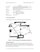
Table of Figures Figure 1 - Vehicle Location and Tracking System Architecture ....................................... 7 Figure 2 - Vehicle Transceiver Unit (VTU)....................................................................... 9 Figure 3 VTU INPUT PIN DEFINITIONS - 10 pin BROWN Molex Connector ............... 11 Figure 4 VTU POWER CONNECTOR PIN DEFINITIONS - 4 pin WHITE Molex Connector ..............................................................................................................
Galaxy Tracking Systems, L.L.C. Technical Documentation - VTU 1.0 INTRODUCTION This document is intended to provide a description of the operation and interfaces of the Vehicle Transceiver Unit (VTU. 2.0 SCOPE This document describes the operation and use of the Vehicle Transceiver Unit (VTU). 3.
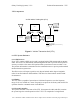
Galaxy Tracking Systems, L.L.C. Technical Documentation - VTU Options Input Switch Box: Antennas: Backup Battery: Connects to V-Trak™, Provides driver with Panic Button / assistance request functions; alternatively used for status indications High current relays allow V-Trak™ outputs to be used to control vehicle: engine kill, unlock door, honk horn, etc.
Galaxy Tracking Systems, L.L.C. Technical Documentation - VTU Vehicles equipped with VTUs can be commanded to continuously report their position, speed, and status. For anti-theft and security related applications, the VTU can provide limited remote control of vehicle systems (e.g., lights, horn or ignition), as well as automated and manual alarms. 5.
Galaxy Tracking Systems, L.L.C.
Galaxy Tracking Systems, L.L.C. Technical Documentation - VTU embedded controller equipped with a Motorola M68HC11E1 microcontroller, 32 Kilobytes of flash ROM, 32 Kilobytes of SRAM and various support components to enable the circuitry to perform the desired tasks. In addition, the baseband board is equipped with a MX-COM 909A single chip GMSK data pump modem for the purpose of providing the communications subsystem with modulation and Forward Error Correction (FEC) for data transmission and reception.
Galaxy Tracking Systems, L.L.C. Technical Documentation - VTU 7.
Galaxy Tracking Systems, L.L.C. Technical Documentation - VTU Figure 4 VTU POWER CONNECTOR PIN DEFINITIONS - 4 pin WHITE Molex Connector Pin 1 2 3 4 Function Chassis Ground VCC +12V No Connection Ignition Sense-- +12V if engine on/ 0 V if off Use or disclosure of data contained on this sheet is subject to the restriction on the title page of this report.
Galaxy Tracking Systems, L.L.C. Technical Documentation - VTU Figure 5 VTU OUTPUT PIN DEFINITIONS - 8 pin BROWN Molex Connector Pin 1 2 3 4 5 6 7 8 Function Power / Transmit LED (Connect anode of LED to this pin, cathode to pin 9 of the 10 pin Molex or other ground point) Illuminates when unit is powered, blinks off during transmit.
Galaxy Tracking Systems, L.L.C. Technical Documentation - VTU between the armed and disarmed states. The remaining input is used to sense activation of the vehicle alarm system (if present). 7.2 Outputs Each of the three Switch Box switches have an associated status LED output (pins 5-7 on J1). When one of the silent alarm switches is pressed, the corresponding LED will flash at a 1 Hz rate to indicate an alarm has been sent to the command center.
Galaxy Tracking Systems, L.L.C. Technical Documentation - VTU Once the VTU has been initialized the first time, it will be able to reinitialize within a minute unless it has been disconnected from vehicle battery power for a long period of time (greater than a week). 8.2 VTU Operating Modes The VTU operates in one of two modes, IN SERVICE or OUT OF SERVICE. In either mode, the VTU receives commands over the UHF radio link from the command center.
Galaxy Tracking Systems, L.L.C. Technical Documentation - VTU ONE SHOT The one-shot command is a request for a single position / status report. The VTU responds with a single IN SERVICE message containing current status, position, speed and time. ACTIVATE TRACKING The ACTIVATE TRACKING command causes the VTU to begin regular position reporting. The rate and the exact moment at which the VTU reports and the frequency on which the report is transmitted are all contained in the command.
Galaxy Tracking Systems, L.L.C. Technical Documentation - VTU option), movement of the vehicle beyond a few hundred feet or at speeds in excess of 20 KPH will trigger a SELF-ACTIVATION. If the vehicle has an alarm system with an appropriate output signal, it can be connected to the VTU. Triggering the vehicle alarm will then also generate a SELF-ACTIVATION.