
User Manual


Galaxy Tracking Systems, L.L.C. VTU User’s Guide
5
Use or disclosure of data contained on this sheet is subject to the restriction on the title page of this report.
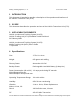
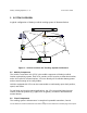
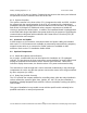
6 VTU Components
GPS Subsys tem
(GPS Receiv er)
Digital B aseba nd
Subsyst em
(Micro Controller)
p,v,t
ID, stat us
Communicatio ns
Subsystem
(Radio Modem)
Packets ,
Timing data /
control
Feat ures
3 Freq between (450-470 Mhz)
9600 ba ud GMSK mod ulati on
Forward Error Correcti on (Hamming c ode, Data Interleavi ng)
2 watt transmit power
20 K range
GPS
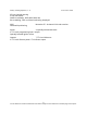
VLaTS Vehicle Tracking Unit (VTU)
p,v,t, ID,st atus
Commands,
Timing
Stat us Inclu des:
H ardware st at us
GPS Tracki ng s tat us
Discretes status
Configurati on,
Initialization,
GPS Correcti ons
Vehicl e
Movement,
SOS,
Assistance,
Car Alarm
Unauthoriz ed Mov ement
Armed,
SOS,
Assistance
Discretes Indicators
UHF
Figure 2 - Vehicle Transceiver Unit (VTU)
6.1 VTU System Enclosure
6.1.1 GPS Receiver
Every VTU contains a GPS receiver and is equipped with a GPS antenna and an
antenna cable. The receiver is differentially aided through the RF link to provide vehicle
position accuracy to within a few meters and synchronized system time accurate to
within .5 ms. The position information is transmitted to the command center at a precise
predetermined moment based on system time.
The GPS receiver will report a position at 0 degrees latitude and 0 degrees longitude
unless it can find and track GPS satellites. This takes less than a minute under normal
circumstances, but can take up to a half an hour the first time the VTU is turned on. It is
recommended that the VTU equipped vehicle be allowed to remain stationary for 15
minutes, with a clear view of the sky, the first time it is powered up.
6.1.2 Radio
The VTU radio is capable of operation on 16 distinct frequencies over the frequency