
Service Manual
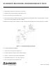

ALIGNMENT PROCEDURE AND PERFORMANCE TESTS
6-5
Part No. 001-3474-002
NOTE: Maintain these deviation levels throughout the test when measuring AC levels, SINAD and
% distortion.
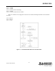
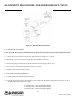
3. Adjust L242 for 2.5V DC (±0.05V DC) at the receive audio output.
4. Set the RF signal generator level to -105 dBm, “unmodulated”.
5. Set the generator frequency 3 kHz below channel center (-X10) or 5 kHz below channel center (-X20/-X30).
6. Adjust C232, then L222 for peak RSSI voltage.
NOTE: Use 2V scale on DVM.
7. Set the RF signal generator frequency back to channel center at -47 dBm with standard deviation level.
8. Adjust L224 for minimum distortion.
9. Set the RF signal generator to -105 dBm, “unmodulated”.
10.Adjust L222 for peak RSSI voltage.
NOTE: Use 2V scale on DVM.
11 Adjust deviation to the level in Step 2. Record the RMS voltage level _______RMS. (Typically 300 mV ±50
mV.)
12.Record the percent distortion _______%. (Typically <3%.)
13.Adjust the RF input level until 12 dB SINAD is measured. (Typically <0.45 µV).
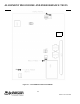
14. Adjust the generator RF level to -120 dBm and measure DC (RSSI) voltage on J201, pin 12. (Typically ≤ 0.90V
DC.)
15.Adjust the generator RF level to -60 dBm and measure DC (RSSI) voltage on J201, pin 12. (Typically ≥ 2.40V
DC.)