
Service Manual
ALIGNMENT PROCEDURE AND PERFORMANCE TESTS
6-2
Part No. 001-3474-002
6. Adjust R542 clockwise for 2.30V DC (+0/-0.1V DC).
7. Readjust C553 counterclockwise for minimum current.
8. Tune C527 clockwise for maximum power.
9. Tune C553 clockwise for 2.0W (±0.1W). Current should be less than 900 mA. (Power output should be 1.6-2.4W
and current less than 900 mA from 403-512 MHz.)
10. Monitor the frequency with a frequency counter and adjust TCXO (Y801) for the channel frequency ±100 Hz.
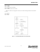
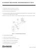
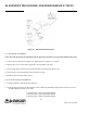
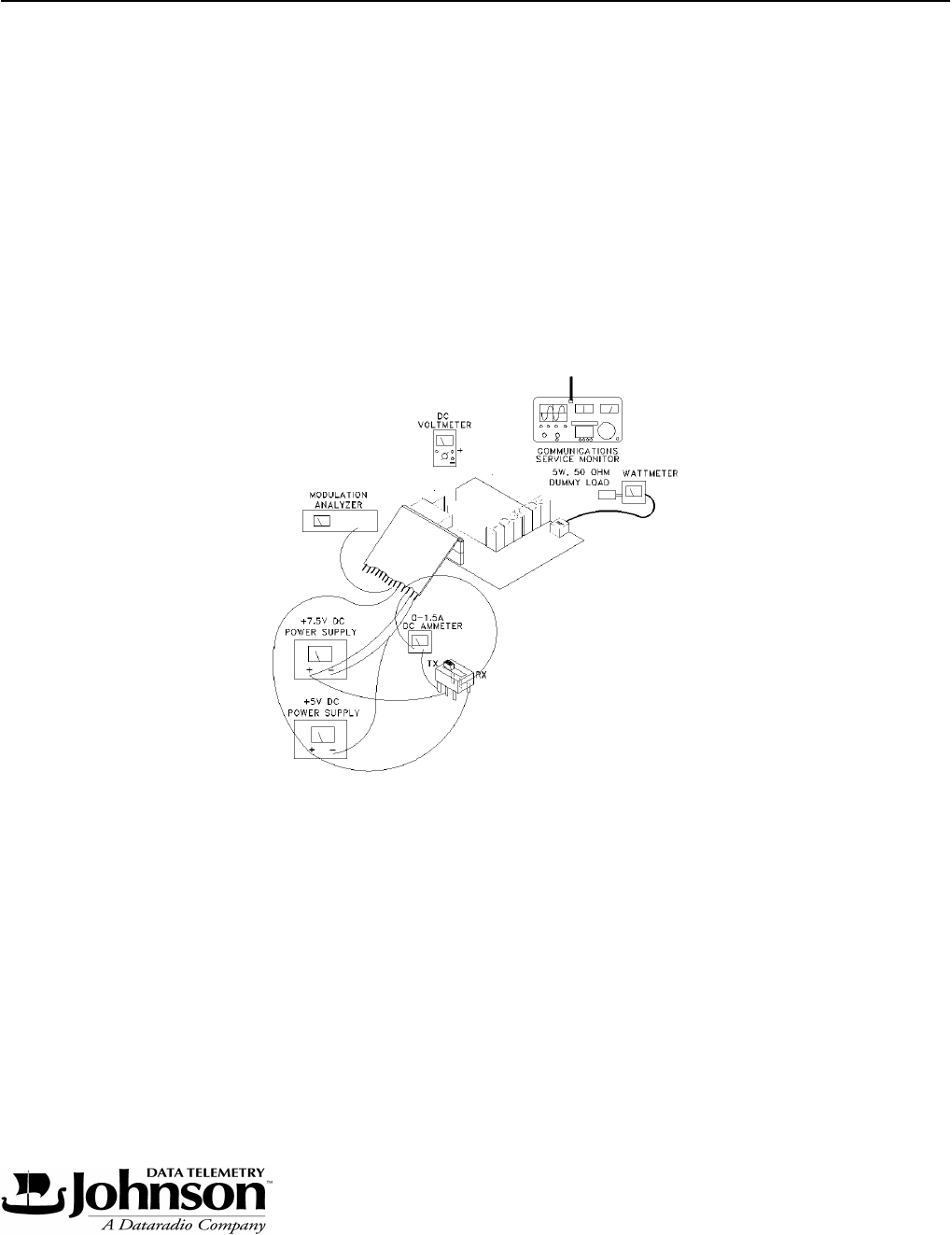
Figure 6-1 TRANSMITTER TEST SETUP
6.2.3 LOW POWER ALIGNMENT
1. Connect the test setup shown in Figure 6-1.
2. Load the synthesizer with the center channel frequency.
3. Connect a voltmeter to the junction of R542/R543.
4. Adjust R542 clockwise for -1.5V DC (±0.1V DC).
5. Tune C527 clockwise for maximum power.