
Service Manual
SERVICING
5-4
Part No. 001-3474-002
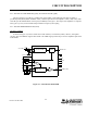
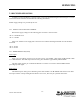
Figure 5-1 RECEIVER SERVICING FLOWCHART
5.3.3 RF AMPLIFIER (Q201) AND FIRST MIXER (Q221)
Refer to the schematic diagram for signal levels and test points for measuring levels.
5.3.4 RF AND IF AMPLIFIERS, FIRST MIXER
Check the DC voltages shown on the schematic diagram. If they are normal, inject a signal at the input and
output of each stage using a .01 µF coupling capacitor. If the stage is producing gain, the injection level on the
input of a stage should be less than that required on the output to produce the same SINAD at the receive output.
5.4 TRANSMITTER SERVICING
5.4.1 SUPPLY VOLTAGES AND CURRENT
Measure the supply voltages on the following pins of interface connector J201: