
Service Manual
SERVICING
5-3
Part No. 001-3474-002
5.3 RECEIVER SERVICING
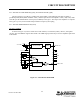
To isolate a receiver problem to a specific section, refer to the troubleshooting flowchart in Figure 5-1. Tests
referenced in the flowchart are described in the following information.
NOTE: Supply voltages are provided by the user.
5.3.1 SUPPLY VOLTAGES AND CURRENT
Measure the supply voltages on the following pins at interface connector J201:
Pin 4 - 5.0V DC Receive
Pin 5 - 5.0V DC
Place a DC ammeter in the supply line to the transceiver and the following maximum currents should be
measured:
Pin 4 - 10 mA
Pin 5 - 50 mA
5.3.2 MIXER/DETECTOR (U201)
Data Output
Using a .01 µF coupling capacitor, inject at U241, pin 16, a 52.95 MHz, 1 mV signal, modulated with 1 kHz
at ± 3 kHz deviation. The audio output level at U241, pin 9 should be approximately 400 mV RMS.
The data output on J201, pin 13 should be 600 mV to 1.2V P-P or 212 mV to 424 mV RMS with the
preceding injection signal.
RSSI Output
The RSSI output on J201, pin 12 should be greater than 100 mV at 12 dB SINAD and less than 2.5V with 1
mV input. If either of the preceding measurements is not correct, there may be a problem with U241.