
Service Manual
CIRCUIT DESCRIPTION
4-9
Part No. 001-3474-002
4.3.4 SECOND LO AMP/TRIPLER (Q401), SECOND IF FILTER (Q901)
The input frequency to Q401 is 17.5 MHz from TCXO Y801 coupled through C402. Bias for Q401 is
provided by R401, R402, R403 and R404. C403, C404 decouple RF from the amplifier. L401, L402, C405, C406
and C407 pass the third harmonic of the input (52.5 MHz) to U241, pin 1. The output of the amplifier is coupled to
U241, pin 1 by C241, and C410 and L404 provided low frequency decoupling.
4.3.5 SECOND MIXER/DETECTOR (U241)
Oscillator and Mixer
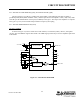
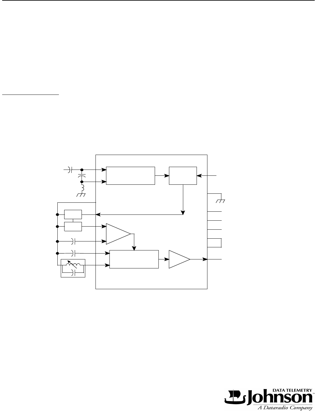
As shown in Figure 4-3, U241 contains the second oscillator, second mixer, limiter, detector, and squelch
circuitry. The 52.95 MHz IF signal is mixed with a 52.5 MHz signal produced by second LO amplifier Q401 from
TCXO Y801.
Figure 4-3 U241 BLOCK DIAGRAM
1
2
3
4
DEMODULATOR
MIXEROSCILLATOR
5
6
7
8
LIMITER
AMP
AMP
16
15
14
13
10
12
11
9
AUDIO OUT
NC
NC
MIXER IN
L242
C243
C242
Z241
Z242
52.5 MHz
C410
L404
C241
AF
RSSI
5.5V CONT