
Installation Instruction
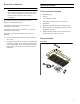
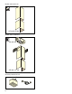
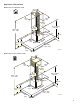
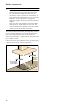
Table Of Contents
- AW 442 720 AW 442 760
- Table of ContentsInstallation instructions
- IMPORTANT SAFETY INSTRUCTIONS
- Installation preparation
- General NotesGeneral Notes
- Before you beginBefore you begin
- Installation
- Appliance Handling Safety
- Installation preparation
- Fitting the wall retainer
- Installing the appliance
- 2 For combination with internal remote fan unit AR 400 743 only: Unscrew the cover plate from the ventilation hood: Loosen the four screws, remove the cover plate and screw the four screws in again.
- 3 For a combination with external remote fan unit AR4.. only: Use the network cable to connect the external remote fan unit and the ventilation hood’s control module. The plug must snap into place. Connect the mains cable to the control module.
- 4 Hook the ventilation hood into both brackets in such a way that it snaps firmly into place.
- 5 Turn the mounting brackets to align the ventilation hood horizontally. If required, the appliance can be moved to the right or to the left.
- 7 Use two screws above the mounting brackets and an additional two screws in the lower section of the ventilation hood to secure it to the wall.
- Recirculation mode units with internal remote fan unit AR 400 743:
- Extraction mode unit with internal remote fan unit AR 400 743
- Extraction mode units without internal remote fan unit AR 400 743
- 1 Unscrew the connecting pieces from the cover plate in the ventilation hood. Secure the exhaust air pipe to the connecting piece. Screw the connecting piece to the cover plate in the ventilation hood.
- 2 Connect it to the air extractor opening.
- 3 Seal the joints appropriately.
- Connecting the power supply
- Attaching flue duct
- 2 Fit the upper flue duct.
- 3 Fit the lower flue duct.
- 5 Fit the grease filter.
- Customer Service
- To book a service visit and product advice
- Appliance Handling Safety
- Table des matièresNotice de montage
- CONSIGNES DE SÉCURITÉ IMPORTANTES
- AVERTISSEMENT
- AVERTISSEMENT
- AVERTISSEMENT
- AVERTISSEMENT
- AVERTISSEMENT
- Risque d'incendie
- AVERTISSEMENT
- Risque d’incendie
- AVERTISSEMENT
- AVERTISSEMENT
- AVERTISSEMENT
- AVERTISSEMENT
- Remarque :
- Sécurité de manutention des appareils
- Codes et normes de sécurité
- Sécurité électrique
- Équipement de sécurité
- Avertissement issu de la proposition 65 :
- Préparatifs du montage
- Instructions GénéralesInstructions Générales
- Avant de commencerAvant de commencer
- Installation
- Sécurité de manutention des appareils
- Préparatifs du montage
- Montage de la fixation murale
- Montage de l'appareil
- 2 Uniquement pour la comvinaison avec moteur séparé interne AR 400 743: Dévissez la tôle de recouvrement dans la hotte : desserrez 4 vis, retirez la tôle de recouvrement, revissez 4 vis.
- 3 Uniquement pour la combinaison avec moteur séparé externe AR 4.. : Raccordez le moteur séparé externe et le module de commande de la hotte avec le câble secteur. Les fiches doivent s’enclencher. Raccordez le câble secteur au module de commande
- 4 Accrochez la hotte dans les deux suspensions de sorte qu’elle s’y engage fermement.
- 5 Alignez la hotte à l’horizontale en tournant les suspensions. Au besoin, il est possible de décaler l’appareil vers la droite ou vers la gauche.
- 7 Bloquez la hotte sur le mur avec deux vis via les suspensions mais aussi avec deux vis dans la partie inférieure de la hotte.
- Modèles à mode recyclage avec moteur séparé interne AR 400 743
- Modèles de mode évacuation avec monteur séparé interne AR 400 743
- Modèles de mode évacuation sans monteur séparé interne AR 400 743
- 1 Dévissez la pièce de connexion de la tôle de recouvrement dans la hotte. Fixez le conduit d'évacuation sur la pièce de connexion. Vissez fermement la pièce de connexion sur la tôle de recouvrement dans la hotte.
- 2 Réalisez la jonction vers l'orifice d'évacuation d'air.
- 3 Étanchéifiez les zones de jonction de façon appropriée.
- Effectuer le raccordement électrique
- Montage du capot de cheminée
- 2 Monter le capot de cheminée supérieur.
- 3 Monter le capot de cheminée inférieur.
- 5 Mettre en place le filtre à graisse.
- Sortie de commutation supplémentaire
- Raccord pour le contacteur de fenêtre AA 400 510
- Utilisation en réseau
- 1 Dévisser la tôle de protection.
- 2 Appuyer sur la touche Réinitialiser (Reset) jusqu'à ce que les deux DEL soient allumées en continu (env. 5 secondes). Relâcher ensuite la touche dans les 5 secondes.
- 3 Visser la tôle de protection.
- 4 Faire vérifier le fonctionnement de l'installation par un technicien qualifié après l'initialisation.
- 1 Dévisser la tôle de protection.
- Brancher l'alimentation électrique
- Démontage de l'appareil
- Service après-vente
- Demande de réparation et conseils en cas de dysfonctionnement
- Sécurité de manutention des appareils
- ÍndiceInstrucciones de instalación
- INSTRUCCIONES DE SEGURIDAD IMPORTANTES
- ADVERTENCIA
- ADVERTENCIA
- ADVERTENCIA
- ADVERTENCIA
- ADVERTENCIA
- Peligro de incendio
- ADVERTENCIA
- Riesgo de incendio
- ADVERTENCIA
- ADVERTENCIA
- ADVERTENCIA
- ADVERTENCIA
- Nota:
- Seguridad de manejo del electrodoméstico
- Códigos y normas de seguridad
- Seguridad eléctrica
- Seguridad del equipo relacionado
- Advertencia en virtud de la Proposición 65:
- Preparativos para el montaje
- Información GeneralInformación General
- Antes de empezarAntes de empezar
- Instalación
- Seguridad de manejo del electrodoméstico
- Preparativos para el montaje
- Montaje del soporte de la pared
- Montaje del aparato
- 2 Solo en combinación con el motor de ventilador interno AR 400 743: Desatornillar la chapa protectora en la campana extractora: desatornillar los 4 tornillos, retirar la chapa protectora, atornillar de nuevo los 4 tornillos.
- 3 Solo para comvinación con el módulo externo de ventilador AR 4..: conectar el módulo de ventilador externo y el módulo de control de la campana extractora con el cable de red..Los enchufes tienen que encajar. Conectar el cable de red al módulo...
- 4 Enganchar la campana extractora a las dos suspensiones de tal modo que quede encajada firmemente.
- 5 Ajustar horizontalmente la campana extractora girando las suspensiones. En caso necesario, el aparato puede desplazarse hacia la derecha o izquierda.
- 7 Asegurar en la pared la campana extractora con dos tornillos por encima de las suspensiones y adicionalmente con dos tornillos en la parte inferior de la campana extractora.
- Modelos de funcionamiento circulación del aire con módulo del ventilador interno AR 400 743
- Modelos de extracción de aire con módulo del ventilador interno AR 400 743
- Modelos de extracción de aire sin módulo del ventilador interno AR 400 743
- 1 Desatornillarelracordeempalmedelachapaprotectoraen la campana extractora. Sujetar el tubo de salida de aire en el racor de empalme. Atornillar el racor de empalme de la chapa protectora en la campana extractora.
- 2 Establecer la conexión con la abertura de salida de aire.
- 3 Obturar convenientemente los puntos de unión.
- Montaje de la toma de corriente
- Montar los revestimientos de la chimenea
- 2 Montar el revestimiento superior de la chimenea.
- 3 Montar el revestimiento inferior de la chimenea.
- 5 Montar el filtro antigrasa.
- Servicio de atención al cliente

9 IMPORTANT SAFETY INSTRUCTIONS
READ AND SAVE THESE INSTRUCTIONS
4
WARNING
When the hood is operated in exhaust-air mode
simultaneously with a different burner which also makes
use of the same chimney (such as gas, oil or coal-fired
heaters, continuous-flow heaters, hot-water boilers) care
must be taken to ensure that there is an adequate
supply of fresh air which will be needed by the burner
for combustion.
Safe operation is possible provided that the under
pressure in the room where the burner is installed does
not exceed 4 Pa (0.04mbar).
This can be achieved if combustion air can flow through
non-lockable openings, e.g. in doors, windows and via
the air-intake/exhaust-air wall box or by other technical
measures, such as reciprocal interlocking, etc.
WARNING
Avoid carbon monoxide poisoning – Provide adequate
air intake so combustion gases are not drawn back into
the room.
An air-intake/exhaust-air wall box by itself is no
guarantee that the limiting value will not be exceeded.
Note: When assessing the overall requirement, the
combined ventilation system for the entire household
must be taken into consideration. This rule does not
apply to the use of cooking appliances, such as
cooktops and ovens.
CAUTION
For general ventilating use only. Do not use to exhaust
hazardous or explosive materials and vapors.
Risk of damage from condensation back flow. Install
exhaust vent at a slight downward slope away from the
appliance (1° slope).
Appliance Handling Safety
Unit is heavy and requires at least two people or proper
equipment to move.
Hidden surfaces may have sharp edges. Use caution
when reaching behind or under appliance.
WARNING
Risk of injury
The appliance may fall from the wall if it is not attached
properly. All fastening components must be fixed firmly
and securely in place.
Safety Codes and Standards
This appliance complies with the latest version of one or
more of the following standards:
▯ UL 507- Electric Fans
▯ CAN/CSA C22.2No. 113- Fans and Ventilators
It is the responsibility of the installer to determine if
additional requirements and/or standards apply to
specific installations.
Electric Safety
WARNING
GROUNDING INSTRUCTIONS
This appliance must be grounded. In the event of an
electrical short circuit, grounding reduces the risk of
electric shock by providing an escape wire for the
electric current.
This appliance is equipped with a cord having a
grounding wire with a grounding plug. The plug must be
plugged into an outlet that is properly installed and
grounded.
WARNING
Improper grounding can result in a risk of electric
shock. Consult a qualified electrician if the grounding
instructions are not completely understood, or if doubt
exists as to whether the appliance is properly grounded.
Do not use an extension cord. If the power supply cord
is too short, have a qualified electrician install an outlet
near the appliance.