
Installation Guide

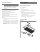
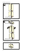
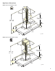
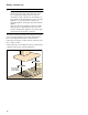
Table Of Contents
- AW 442 720
- Table of ContentsInstallation instructions
- IMPORTANT SAFETY INSTRUCTIONS
- WARNING
- WARNING
- WARNING
- WARNING
- WARNING
- Risk of fire
- WARNING
- Risk of fire
- WARNING
- WARNING
- WARNING
- WARNING
- Note:
- Appliance Handling Safety
- Safety Codes and Standards
- Electric Safety
- Related Equipment Safety
- State of California Proposition 65 Warnings
- Installation preparation
- General notes
- Before You Begin
- Installation
- Installation preparation
- Fitting the wall retainer
- Installing the appliance
- 1 For the air recirculation version only: Fit filters to both sides of the AA 442 810 air recirculation module. Hook the air recirculation module into the angle brackets. Secure it to the wall with two screws.
- 2 For combination with internal remote fan unit AR 400 743 only: Unscrew the cover plate from the ventilation hood: Loosen the four screws, remove the cover plate and screw the four screws in again.
- 3 For a combination with external remote fan unit AR4.. only: Use the network cable to connect the external remote fan unit and the ventilation hood’s control module. The plug must snap into place. Connect the mains cable to the control module.
- Note:
- 4 Hook the ventilation hood into both brackets in such a way that it snaps firmly into place.
- 5 Turn the mounting brackets to align the ventilation hood horizontally. If required, the appliance can be moved to the right or to the left.
- 6 Tighten the screws on the mounting brackets. To do this, hold the mounting brackets in place to prevent them from twisting.
- 7 Use two screws above the mounting brackets and an additional two screws in the lower section of the ventilation hood to secure it to the wall.
- Establishing the connection for the exhaust air
- Connecting the power supply
- Attaching flue duct
- Additional switching output
- Networked operation
- Connect Electrical Supply
- Removing the appliance
- Customer service
- Table de MatièresInstructions d’installation
- CONSIGNES DE SÉCURITÉ IMPORTANTES
- AVERTISSEMENT
- AVERTISSEMENT
- AVERTISSEMENT
- AVERTISSEMENT
- AVERTISSEMENT
- Risque d'incendie
- AVERTISSEMENT
- Risque d’incendie
- AVERTISSEMENT
- AVERTISSEMENT
- AVERTISSEMENT
- AVERTISSEMENT
- Remarque :
- Sécurité de manipulation de l'appareil
- Codes et normes de sécurité
- Sécurité électrique
- Sécurité apparentée concernant l'équipement
- Avertissements de la Proposition 65 de l’État de la Californie
- Préparatifs du montage
- Instructions générales
- Avant de commencer
- Installation
- Préparatifs du montage
- Montage de la fixation murale
- Montage de l'appareil
- 1 Uniquement pour la version à recyclage: Filter beidseitig in das Umluftmodul AA 442 810 einsetzen. Accrochez le module de recyclage de l’air dans les cornières. Fixez-le contre le mur avec 2 vis.
- 2 Uniquement pour la comvinaison avec moteur séparé interne AR 400 743: Dévissez la tôle de recouvrement dans la hotte : desserrez 4 vis, retirez la tôle de recouvrement, revissez 4 vis.
- 3 Uniquement pour la combinaison avec moteur séparé externe AR 4.. : Raccordez le moteur séparé externe et le module de commande de la hotte avec le câble secteur. Les fiches doivent s’enclencher. Raccordez le câble secteur au module de commande
- Remarque :
- 4 Accrochez la hotte dans les deux suspensions de sorte qu’elle s’y engage fermement.
- 5 Alignez la hotte à l’horizontale en tournant les suspensions. Au besoin, il est possible de décaler l’appareil vers la droite ou vers la gauche.
- 6 Vissez fermement les vis des suspensions. Tout en les maintenant pour éviter qu’elles ne pivotent.
- 7 Bloquez la hotte sur le mur avec deux vis via les suspensions mais aussi avec deux vis dans la partie inférieure de la hotte.
- Effectuer le raccordement de l'évacuation de l'air
- Remarques
- Modèles à mode recyclage avec moteur séparé interne AR 400 743
- Modèles de mode évacuation avec monteur séparé interne AR 400 743
- Modèles de mode évacuation sans monteur séparé interne AR 400 743
- 1 Dévissez la pièce de connexion de la tôle de recouvrement dans la hotte. Fixez le conduit d'évacuation sur la pièce de connexion. Vissez fermement la pièce de connexion sur la tôle de recouvrement dans la hotte.
- 2 Réalisez la jonction vers l'orifice d'évacuation d'air.
- 3 Étanchéifiez les zones de jonction de façon appropriée.
- Remarques
- Effectuer le raccordement électrique
- Montage du capot de cheminée
- Sortie de commutation supplémentaire
- Utilisation en réseau
- 1 Dévisser la tôle de protection.
- 2 Appuyer sur la touche Réinitialiser (Reset) jusqu'à ce que les deux DEL soient allumées en continu (env. 5 secondes). Relâcher ensuite la touche dans les 5 secondes.
- 3 Visser la tôle de protection.
- 4 Faire vérifier le fonctionnement de l'installation par un technicien qualifié après l'initialisation.
- Brancher l'alimentation électrique
- Démontage de l'appareil
- Service après-vente
- ContenidoInstrucciones de instalación
- INSTRUCCIONES DE SEGURIDAD IMPORTANTES
- ADVERTENCIA
- ADVERTENCIA
- ADVERTENCIA
- ADVERTENCIA
- ADVERTENCIA
- Peligro de incendio
- ADVERTENCIA
- Riesgo de incendio
- ADVERTENCIA
- ADVERTENCIA
- ADVERTENCIA
- ADVERTENCIA
- Nota:
- Seguridad con el manejo del electrodoméstico
- Códigos y normas de seguridad
- Seguridad con la electricidad
- Seguridad relacionada con los equipos
- Advertencias en virtud de la Proposición 65 del estado de California
- Preparativos para el montaje
- Información general
- Antes de empezar
- Instalación
- Preparativos para el montaje
- 1 Dibujar en la pared una línea central vertical desde el techo hasta el borde inferior de la campana extractora.
- 2 Dibujar las posiciones para los tornillos y el contorno de la zona de enganche.
- 3 Taladrar los orificios para las fijaciones e introducir los taquetes de tal manera que queden enrasados con la pared.
- Montaje del soporte de la pared
- Montaje del aparato
- 1 Solo para versión de recirculación de aire: introducir el filtro en ambos lados del módulo de recirulación de aire AA 442 810. Enganchar el módulo de recirculación de aire a la escuadra de sujeción. Sujetar a la pared con 2 tornillos.
- 2 Solo en combinación con el motor de ventilador interno AR 400 743: Desatornillar la chapa protectora en la campana extractora: desatornillar los 4 tornillos, retirar la chapa protectora, atornillar de nuevo los 4 tornillos.
- 3 Solo para comvinación con el módulo externo de ventilador AR 4..: conectar el módulo de ventilador externo y el módulo de control de la campana extractora con el cable de red. .Los enchufes tienen que encajar. Conectar el cable de red al módul...
- Nota:
- 4 Enganchar la campana extractora a las dos suspensiones de tal modo que quede encajada firmemente.
- 5 Ajustar horizontalmente la campana extractora girando las suspensiones. En caso necesario, el aparato puede desplazarse hacia la derecha o izquierda.
- 6 Apretar los tornillos de las suspensiones. Sujetar las suspensiones para evitar que se giren excesivamente.
- 7 Asegurar en la pared la campana extractora con dos tornillos por encima de las suspensiones y adicionalmente con dos tornillos en la parte inferior de la campana extractora.
- Conexión de la salida de aire
- Notas
- Modelos de funcionamiento circulación del aire con módulo del ventilador interno AR 400 743
- Modelos de extracción de aire con módulo del ventilador interno AR 400 743
- Modelos de extracción de aire sin módulo del ventilador interno AR 400 743
- 1 Desatornillarelracordeempalmedelachapaprotectoraen la campana extractora. Sujetar el tubo de salida de aire en el racor de empalme. Atornillar el racor de empalme de la chapa protectora en la campana extractora.
- 2 Establecer la conexión con la abertura de salida de aire.
- 3 Obturar convenientemente los puntos de unión.
- Notas
- Montaje de la toma de corriente
- Montar los revestimientos de la chimenea
- Salida de conexión adicional
- Funcionamiento conectado
- 1 Desatornillar la tapa protectora.
- 2 Pulsar la tecla Reset hasta que los dos LED se iluminen de forma permanente (aprox. 5 segundos). Después de 5 segundos, soltar la tecla.
- 3 Atornillar la tapa protectora.
- 4 Contactar con profesionales calificados para que comprueben el funcionamiento de la instalación tras el reinicio.
- Conexión de la alimentación eléctrica
- Desmontaje del aparato
- Preparativos para el montaje
- Servicio de atención al cliente

9 IMPORTANT SAFETY INSTRUCTIONS
READ AND SAVE THESE INSTRUCTIONS
4
WARNING
When the hood is operated in exhaust-air mode
simultaneously with a different burner which also makes
use of the same chimney (such as gas, oil or coal-fired
heaters, continuous-flow heaters, hot-water boilers) care
must be taken to ensure that there is an adequate
supply of fresh air which will be needed by the burner
for combustion.
Safe operation is possible provided that the under
pressure in the room where the burner is installed does
not exceed 4 Pa (0.04 mbar).
This can be achieved if combustion air can flow through
non-lockable openings, e.g. in doors, windows and via
the air-intake/exhaust-air wall box or by other technical
measures, such as reciprocal interlocking, etc.
WARNING
Avoid carbon monoxide poisoning – Provide adequate
air intake so combustion gases are not drawn back into
the room.
An air-intake/exhaust-air wall box by itself is no
guarantee that the limiting value will not be exceeded.
Note: When assessing the overall requirement, the
combined ventilation system for the entire household
must be taken into consideration. This rule does not
apply to the use of cooking appliances, such as
cooktops and ovens.
CAUTION
For general ventilating use only. Do not use to exhaust
hazardous or explosive materials and vapors.
Risk of damage from condensation back flow. Install
exhaust vent at a slight downward slope away from the
appliance (1° slope).
Appliance Handling Safety
Unit is heavy and requires at least two people or proper
equipment to move.
Hidden surfaces may have sharp edges. Use caution
when reaching behind or under appliance.
WARNING
Risk of injury
The appliance may fall from the wall if it is not attached
properly. All fastening components must be fixed firmly
and securely in place.
Safety Codes and Standards
This appliance complies with the latest version of one or
more of the following standards:
▯ UL 507 - Electric Fans
▯ CAN/CSA C22.2 No. 113 - Fans and Ventilators
It is the responsibility of the installer to determine if
additional requirements and/or standards apply to
specific installations.
Electric Safety
WARNING
GROUNDING INSTRUCTIONS
This appliance must be grounded. In the event of an
electrical short circuit, grounding reduces the risk of
electric shock by providing an escape wire for the
electric current.
This appliance is equipped with a cord having a
grounding wire with a grounding plug. The plug must be
plugged into an outlet that is properly installed and
grounded.
WARNING
Improper grounding can result in a risk of electric
shock. Consult a qualified electrician if the grounding
instructions are not completely understood, or if doubt
exists as to whether the appliance is properly grounded.
Do not use an extension cord. If the power supply cord
is too short, have a qualified electrician install an outlet
near the appliance.
WARNING
Before you plug in an electrical cord or turn on power
supply, make sure all controls are in the OFF position.