
Installation Guide

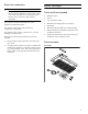
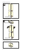
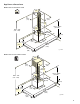
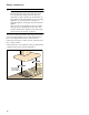
Table Of Contents
- AW 442 720
- Table of ContentsInstallation instructions
- IMPORTANT SAFETY INSTRUCTIONS
- WARNING
- WARNING
- WARNING
- WARNING
- WARNING
- Risk of fire
- WARNING
- Risk of fire
- WARNING
- WARNING
- WARNING
- WARNING
- Note:
- Appliance Handling Safety
- Safety Codes and Standards
- Electric Safety
- Related Equipment Safety
- State of California Proposition 65 Warnings
- Installation preparation
- General notes
- Before You Begin
- Installation
- Installation preparation
- Fitting the wall retainer
- Installing the appliance
- 1 For the air recirculation version only: Fit filters to both sides of the AA 442 810 air recirculation module. Hook the air recirculation module into the angle brackets. Secure it to the wall with two screws.
- 2 For combination with internal remote fan unit AR 400 743 only: Unscrew the cover plate from the ventilation hood: Loosen the four screws, remove the cover plate and screw the four screws in again.
- 3 For a combination with external remote fan unit AR4.. only: Use the network cable to connect the external remote fan unit and the ventilation hood’s control module. The plug must snap into place. Connect the mains cable to the control module.
- Note:
- 4 Hook the ventilation hood into both brackets in such a way that it snaps firmly into place.
- 5 Turn the mounting brackets to align the ventilation hood horizontally. If required, the appliance can be moved to the right or to the left.
- 6 Tighten the screws on the mounting brackets. To do this, hold the mounting brackets in place to prevent them from twisting.
- 7 Use two screws above the mounting brackets and an additional two screws in the lower section of the ventilation hood to secure it to the wall.
- Establishing the connection for the exhaust air
- Connecting the power supply
- Attaching flue duct
- Additional switching output
- Networked operation
- Connect Electrical Supply
- Removing the appliance
- Customer service
- Table de MatièresInstructions d’installation
- CONSIGNES DE SÉCURITÉ IMPORTANTES
- AVERTISSEMENT
- AVERTISSEMENT
- AVERTISSEMENT
- AVERTISSEMENT
- AVERTISSEMENT
- Risque d'incendie
- AVERTISSEMENT
- Risque d’incendie
- AVERTISSEMENT
- AVERTISSEMENT
- AVERTISSEMENT
- AVERTISSEMENT
- Remarque :
- Sécurité de manipulation de l'appareil
- Codes et normes de sécurité
- Sécurité électrique
- Sécurité apparentée concernant l'équipement
- Avertissements de la Proposition 65 de l’État de la Californie
- Préparatifs du montage
- Instructions générales
- Avant de commencer
- Installation
- Préparatifs du montage
- Montage de la fixation murale
- Montage de l'appareil
- 1 Uniquement pour la version à recyclage: Filter beidseitig in das Umluftmodul AA 442 810 einsetzen. Accrochez le module de recyclage de l’air dans les cornières. Fixez-le contre le mur avec 2 vis.
- 2 Uniquement pour la comvinaison avec moteur séparé interne AR 400 743: Dévissez la tôle de recouvrement dans la hotte : desserrez 4 vis, retirez la tôle de recouvrement, revissez 4 vis.
- 3 Uniquement pour la combinaison avec moteur séparé externe AR 4.. : Raccordez le moteur séparé externe et le module de commande de la hotte avec le câble secteur. Les fiches doivent s’enclencher. Raccordez le câble secteur au module de commande
- Remarque :
- 4 Accrochez la hotte dans les deux suspensions de sorte qu’elle s’y engage fermement.
- 5 Alignez la hotte à l’horizontale en tournant les suspensions. Au besoin, il est possible de décaler l’appareil vers la droite ou vers la gauche.
- 6 Vissez fermement les vis des suspensions. Tout en les maintenant pour éviter qu’elles ne pivotent.
- 7 Bloquez la hotte sur le mur avec deux vis via les suspensions mais aussi avec deux vis dans la partie inférieure de la hotte.
- Effectuer le raccordement de l'évacuation de l'air
- Remarques
- Modèles à mode recyclage avec moteur séparé interne AR 400 743
- Modèles de mode évacuation avec monteur séparé interne AR 400 743
- Modèles de mode évacuation sans monteur séparé interne AR 400 743
- 1 Dévissez la pièce de connexion de la tôle de recouvrement dans la hotte. Fixez le conduit d'évacuation sur la pièce de connexion. Vissez fermement la pièce de connexion sur la tôle de recouvrement dans la hotte.
- 2 Réalisez la jonction vers l'orifice d'évacuation d'air.
- 3 Étanchéifiez les zones de jonction de façon appropriée.
- Remarques
- Effectuer le raccordement électrique
- Montage du capot de cheminée
- Sortie de commutation supplémentaire
- Utilisation en réseau
- 1 Dévisser la tôle de protection.
- 2 Appuyer sur la touche Réinitialiser (Reset) jusqu'à ce que les deux DEL soient allumées en continu (env. 5 secondes). Relâcher ensuite la touche dans les 5 secondes.
- 3 Visser la tôle de protection.
- 4 Faire vérifier le fonctionnement de l'installation par un technicien qualifié après l'initialisation.
- Brancher l'alimentation électrique
- Démontage de l'appareil
- Service après-vente
- ContenidoInstrucciones de instalación
- INSTRUCCIONES DE SEGURIDAD IMPORTANTES
- ADVERTENCIA
- ADVERTENCIA
- ADVERTENCIA
- ADVERTENCIA
- ADVERTENCIA
- Peligro de incendio
- ADVERTENCIA
- Riesgo de incendio
- ADVERTENCIA
- ADVERTENCIA
- ADVERTENCIA
- ADVERTENCIA
- Nota:
- Seguridad con el manejo del electrodoméstico
- Códigos y normas de seguridad
- Seguridad con la electricidad
- Seguridad relacionada con los equipos
- Advertencias en virtud de la Proposición 65 del estado de California
- Preparativos para el montaje
- Información general
- Antes de empezar
- Instalación
- Preparativos para el montaje
- 1 Dibujar en la pared una línea central vertical desde el techo hasta el borde inferior de la campana extractora.
- 2 Dibujar las posiciones para los tornillos y el contorno de la zona de enganche.
- 3 Taladrar los orificios para las fijaciones e introducir los taquetes de tal manera que queden enrasados con la pared.
- Montaje del soporte de la pared
- Montaje del aparato
- 1 Solo para versión de recirculación de aire: introducir el filtro en ambos lados del módulo de recirulación de aire AA 442 810. Enganchar el módulo de recirculación de aire a la escuadra de sujeción. Sujetar a la pared con 2 tornillos.
- 2 Solo en combinación con el motor de ventilador interno AR 400 743: Desatornillar la chapa protectora en la campana extractora: desatornillar los 4 tornillos, retirar la chapa protectora, atornillar de nuevo los 4 tornillos.
- 3 Solo para comvinación con el módulo externo de ventilador AR 4..: conectar el módulo de ventilador externo y el módulo de control de la campana extractora con el cable de red. .Los enchufes tienen que encajar. Conectar el cable de red al módul...
- Nota:
- 4 Enganchar la campana extractora a las dos suspensiones de tal modo que quede encajada firmemente.
- 5 Ajustar horizontalmente la campana extractora girando las suspensiones. En caso necesario, el aparato puede desplazarse hacia la derecha o izquierda.
- 6 Apretar los tornillos de las suspensiones. Sujetar las suspensiones para evitar que se giren excesivamente.
- 7 Asegurar en la pared la campana extractora con dos tornillos por encima de las suspensiones y adicionalmente con dos tornillos en la parte inferior de la campana extractora.
- Conexión de la salida de aire
- Notas
- Modelos de funcionamiento circulación del aire con módulo del ventilador interno AR 400 743
- Modelos de extracción de aire con módulo del ventilador interno AR 400 743
- Modelos de extracción de aire sin módulo del ventilador interno AR 400 743
- 1 Desatornillarelracordeempalmedelachapaprotectoraen la campana extractora. Sujetar el tubo de salida de aire en el racor de empalme. Atornillar el racor de empalme de la chapa protectora en la campana extractora.
- 2 Establecer la conexión con la abertura de salida de aire.
- 3 Obturar convenientemente los puntos de unión.
- Notas
- Montaje de la toma de corriente
- Montar los revestimientos de la chimenea
- Salida de conexión adicional
- Funcionamiento conectado
- 1 Desatornillar la tapa protectora.
- 2 Pulsar la tecla Reset hasta que los dos LED se iluminen de forma permanente (aprox. 5 segundos). Después de 5 segundos, soltar la tecla.
- 3 Atornillar la tapa protectora.
- 4 Contactar con profesionales calificados para que comprueben el funcionamiento de la instalación tras el reinicio.
- Conexión de la alimentación eléctrica
- Desmontaje del aparato
- Preparativos para el montaje
- Servicio de atención al cliente

3
9 IMPORTANT SAFETY INSTRUCTIONS
READ AND SAVE THESE INSTRUCTIONS
IMPORTANT SAFETY
READ AND SAVE THESE INSTRUCTIONS
INSTALLER: LEAVE THESE INSTRUCTIONS WITH
THE APPLIANCE AFTER INSTALLATION IS
COMPLETE.
IMPORTANT: SAVE THESE INSTRUCTIONS FOR THE
LOCAL ELECTRICAL INSPECTOR'S USE.
WARNING
If the information in this manual is not followed exactly,
fire or shock may result causing property damage or
personal injury.
WARNING
Do not repair, replace or remove any part of the
appliance unless specifically recommended in the
manuals. Improper installation, service or maintenance
can cause injury or property damage. Refer to this
manual for guidance. All other servicing should be done
by a qualified technician.
WARNING
WARNING – TO REDUCE THE RISK OF FIRE,
ELECTRIC SHOCK, OR INJURY TO PERSONS,
OBSERVE THE FOLLOWING
‒ Installation work and electrical wiring must be done
by qualified person(s) in accordance with all
applicable codes and standards, including fire-
rated construction.
‒ Sufficient air is needed for proper combustion and
exhausting of gases through the flue (chimney) of
fuel burning equipment to prevent back drafting.
Follow the heating equipment manufacturer’s
guideline and safety standards such as those
published by the National Fire Protection
Association (NFPA), and the American Society for
Heating, Refrigeration and Air Conditioning
Engineers (ASHRAE), and the local code
authorities.
‒ When cutting or drilling into wall or ceiling, do not
damage electrical wiring and other hidden utilities.
‒ Ducted fans must always be vented to the outdoors.
WARNING
The applicable regulations of the energy supply
companies and the regional construction regulations
must be observed when installing the hood.
WARNING
Risk of fire
Grease deposits in the grease filter can catch fire.
Never work with a naked flame near the appliance (e.g.
flambéing). Install the unit near a heat-producing
appliance for solid fuels (e.g. wood or coal) only if there
is a closed, non-detachable cover. There must be no
flying sparks.
WARNING
Risk of fire
Operating several gas burners at the same time gives
rise to a great deal of heat. The ventilation appliance
may become damaged or catch fire. The ventilation
appliance must only be combined with gas burners that
do not exceed the maximum total output of 61,000 Btu/
hr (18 kW). If 41,000 Btu/hr (12 kW) is exceeded, the
local regulations concerning room ventilation, room
size, and combination with ventilation devices in exhaust
and recirculating operation must be heeded.
WARNING
To reduce risk of fire and to properly exhaust air, be
sure to duct air outside. Do not vent exhaust air into
spaces within walls, ceilings, attics, crawl spaces or
garages.
WARNING
To reduce the risk of fire, use only metal ductwork.