
Installation Guide


This will help keep the seam area attached to the hip rafter for increased strength.
The air slot can be widened, in this case, to
5
/
8
” (15.9 mm) on each side of the hip
rafter to maintain proper NFVA.
Subsequent Air Slots: After the top hip air slot is cut, working down the hip, leave
12” (305 mm) of uncut hip. Mark and cut another 2 ½” x 36” (64 mm x 914 mm) air
slot centered on the hip to provide a ½” x 36” (13 mm x 914 mm) opening on each
side of the hip rafter. Continue marking and cutting separated hip air slots, as needed,
until reaching the midpoint of the hip. Depending on the length of the roof’s hip and
ventilation needs, the bottom hip slot nearest the midpoint may be less than 36” (914
mm) in length. Always remember: Do NOT cut slots closer than 24” (610 mm) to the
building’s warm exterior wall.
NOTE: Re-nail or reinforce any tongue-and-groove decking or plywood/OSB sheathing
in the area of the hip air slots, as needed.
STEP 3 – Cobra
®
Hip Vent Installation
For a uniform appearance, install Cobra
®
Hip Vent over the entire length of the hip,
making sure that the vent always extends past the bottom and top hip slot openings
by at least 12” (305 mm).
Install two cap shingles at the base of the hip (nearest the eave edge); these cap
shingles will be underneath the lowermost section of Cobra
®
Hip Vent. This application
helps to ensure that the end of the hip at the eave edge is weather resistant.
Starting at the bottom of the hip nearest the eave: Center and conform Cobra
®
Hip Vent over the shingles, placing it firmly against the roof surface.
IMPORTANT! Always be sure that Cobra
®
Hip Vent is oriented so that the “Towards
Peak” arrows on the top surface of the vent point towards the peak of the roof. This
orientation is critical to help prevent weather infiltration and leaking.
With Cobra
®
Hip Vent properly oriented, fasten the vent in place using the included
1
3
/
4
” (44 mm) pneumatic coil nails (use longer nails if necessary). Nails must always
penetrate through plywood or OSB decks or at least
3
/
4
” (19 mm) into wood planks
and should be driven flush with the surface of the Cobra
®
Hip Vent. The suggested
pneumatic nail gun air pressure is 95-100 PSI. However, a higher or lower pressure
adjustment may be necessary to prevent overdriving or underdriving the nails.
Attach the first Cobra
®
Hip Vent section using appropriate coil nails at the pre-marked
6” (152 mm) increment nail gun targets. These targets are marked “Fasten Vent Here”
on the vent.
Continue fastening Cobra
®
Hip Vent up the hip towards the peak. Apply the subsequent
sections using the vent’s overlap/underlap tabs.
NOTE: For maximum weather resistance, always ensure that Cobra
®
Hip Vent is
fastened tightly and snugly to the roof shingles below.
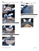
STEP 4 – Hip Termination & Ridge Intersections
Installations Without Ridge Vent: Terminate the top Cobra
®
Hip Vent section
at the top of the hip and approximately level to the ridge line. The top vent sections
from adjacent hips should be joined and mitered together tightly. Install a 3” x 12”
(76 mm x 305 mm) strip of self-adhering leak barrier over all the junctions between
the mitered vents.
Installations With Ridge Vent: Always install the ridge vent before the Cobra
®
Hip Vent. Cut out the template printed on the outside of the Cobra
®
Hip Vent package.
See the Cobra
®
Hip Vent to Ridge Vent Miter Cut Instructions included inside
the package.
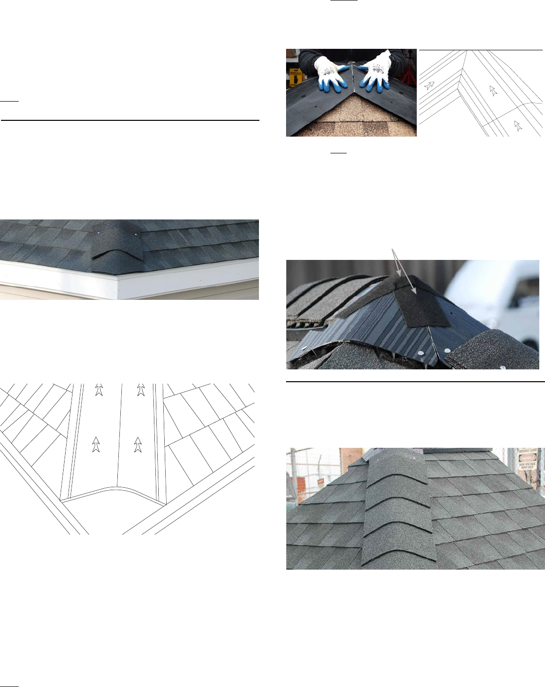
With the top section of the Cobra
®
Hip Vent properly sized and butted tightly to the
ridge vent, fasten in accordance with Step 3. Install a 3” x 12” (76 mm x 305 mm)
strip of self-adhering leak barrier over all junctions between the hip vent and ridge
vent. Proceed with installing cap shingle.
STEP 5 – Cap Shingle Installation
Install the cap shingles directly over the Cobra
®
Hip Vent, using 1
3
/
4
” (44 mm) pneu-
matic coil nails (included) or longer nails if necessary. Follow the nail line on the top of
the vent to make sure to fasten the cap shingles in the right location.
3” x 12” (76 mm x 305 mm) strips of self-adhering leak barrier over all junctions
between the hip vent and ridge vent