
User Manual

XScopes
User’s Manual
DS-XScopes-3.5 – December, 2014 Page | 33
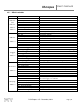
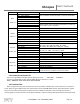
Table 12: XScope Command Set
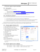
6.4.1 Auto Send
When the Auto send is active, the device
will continuously send the channels data to the
serial port. The “Channels Sent” byte is an
ASCII number that represents which channels were sent, Channel 1 will add 1 to the number, Channel 2 will add 2, and the
logic port will add 4. For example, if all channels are sent, the “Channels Sent” will be the character ‘7’.
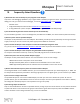
6.4.2 METER measurement data
The METER mode must be enabled in order to receive valid data; the
data sent will depend on which METER mode is selected. In the VDC mode,
the Channel data is in 16bit signed format, the value represents the
millivolts divided by 1.25. In the Frequency Counter mode, the data is in
32bit unsigned format, which represents the counter value.
Command
Description
Device Response / Notes
a
Request firmware version
The device returns 4 characters with the version.
b
Writes a byte to the XScope’s Settings, at the
specified index.
If the Index is below 14, the updatemso bit is
automatically set.
If the Index is above 34, the updateawg is
automatically set.
When using the USB interface, the setup packet’s
Index contains the index, and the setup packet’s
Value contains the data. When using the using the
Serial interface, two additional bytes must be sent
containing the index and data.
c
Sets the desired AWG Frequency (32bits).
When using the USB interface, the Index contains the
lower 16bits, the Value contains the high 16bits.
When using the Serial interface, 4 additional bytes
must be sent in little endian format.
d
Save XScope’s Settings in EEPROM
e
Save AWG wave stored in RAM to EEPROM
f
Stop Scope
g
Start Scope
h
Force Trigger
i
Auto Setup
j
Sets the desired Post Trigger value (16bits)
USB interface: the Value contains the 16bits.
When using the Serial interface, 2 additional bytes
must be sent in little endian format.
k
Restore factory settings
m
Request METER measurement data
The device sends 4 bytes in little endian format.
See the description in section 6.4.2 below.
p
Disable Auto send (Serial interface only)
q
Enable Auto send (Serial interface only)
See the description in section 6.4.1 below.
u
Request settings
All the settings (44 bytes) are sent to the PC.
w
Request EE waveform (Serial interface only)
EE Wave data (256 bytes)
x
Send waveform data
(Serial interface only)
'G' character, signals the PC that the device is ready,
Then the PC sends the data (256 bytes),
Then the device sends a 'T' character, which signals
the PC that the data was received.
C
Request BMP
(Serial interface only)
128x64 Monochrome BMP using the XModem
protocol
Fast Sampling
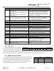
0x0D
0x0A
‘F’
Data
0x0A
0x0D
Channels sent
Slow Sampling
0x0D
0x0A
‘S’
Data
0x0A
0x0D
Channels sent
VDC
FREQUENCY
Byte 0
Channel 1 LB
Freq. Cnt. byte 3
Byte 1
Channel 1 HB
Freq. Cnt. byte 2
Byte 2
Channel 2 LB
Freq. Cnt. byte 1
Byte 3
Channel 2 HB
Freq. Cnt. byte 0
Table 14: METER data
Table 13: Auto Send Packet Format