
User Manual

XScopes
User’s Manual
DS-XScopes-3.5 – December, 2014 Page | 8
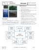
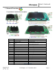
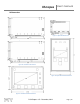
1.2 Xprotolab Portable and Xminilab Portable Overview
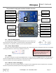
1.2.1 Input Coupling Switch
The coupling switch is electrically placed between the input connector and
the oscilloscope’s input amplifier. The switch selects a direct path for DC or AC
measurements, or a path thru a capacitor, for AC only measurements.
1.2.2 Curve Tracer Switch
This switch connects the AWG to the input channels, this is used in particular for creating V/I curve traces. An example
of setting the device for curve tracing is showed in section 8.5.
1.2.3 MENU / Power button
The device is powered on by pressing the MENU button. To power off, press the MENU button for 2 seconds. Some of
the device modes disable this command, so to power off, set the device in Scope mode. The device is also powered off
when the shutdown timer expires (regardless of the device mode).
1.2.4 USB Port / Device Charging
The USB port is also used to charge the device. The device can be charged either when the powered on or off. When
the device is powered off, the battery can be fully charged in about 2 hours.
Figure 7: Xprotolab Portable
Curve Tracer Switch
Input Coupling Switch
ON
OFF
Analog Inputs
Arbitrary Waveform
External Trigger
Digital Inputs
USB Port /
Device Charging
K3
K1
K2
MENU /
Power button
Figure 9: Input Coupling Switch
Figure 10: Curve Tracer Switch
Do not connect CH2 to a voltage
source while the CURVE switch is on.
Damage to the device will occur.
Curve Tracer Switch
External Trigger
Arbitrary Waveform
Analog Inputs
Input Coupling Switch
Digital Inputs
USB Port /
Device Charging
MENU /
Power button
Figure 8: Xminilab Portable
K1
K2
K3