
User Manual

XScopes
User’s Manual
DS-XScopes-3.5 – December, 2014 Page | 32
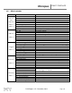
Name
Bits
Notes
MFFT
Index 8
Bit 0: Hamming Window
Only one window must be selected, or none for No Window.
Bit 1: Hann Window
Bit 2: Blackman Window
Bit 3: Vertical Log
Bit 4: IQ FFT
Bit 5: Scope Mode
Multiple modes can be selected simultaneously. If no bits are
set, the Meter mode is displayed.
Bit 6: XY Mode
Bit 7: FFT Mode
Sweep
Index 9
Bit 0: Acceleration Direction
Bit 1: Accelerate Sweep
Bit 2: Sweep Direction
Bit 3: Ping Pong Mode
Bit 4: Sweep Frequency
Bit 5: Sweep Amplitude
Bit 6: Sweep Offset
Bit 7: Sweep Duty Cycle
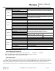
Sniffer
Index 10
Bit 0: Baud 0
UART Sniffer Baud Rates:
000: 1200 , 001: 2400, 010: 4800, 011: 9600,
100: 19200, 101: 38400, 110: 57600, 111: 115200
Bit 1: Baud 1
Bit 2: Baud 2
Bit 3: Uart 0
UART Data bits:
00: 5 Bits , 01: 6 Bits , 10: 7 Bits , 11: 8 Bits
Bit 4: Uart 1
Bit 5: Parity Mode / SS Invert
Enables UART parity check
SPI Invert Slave Select
Bit 6: Parity / CPOL Clock Polarity
UART Parity Odd (1), Parity Even (0)
SPI Clock Polarity
Bit 7: Stop Bit / CPOH Clock Phase
1 Stop bit (0), 2 Stop bits (1)
SPI Clock Phase
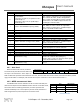
MStatus
Index 11
Bit 0: Update
Exits triggering if the bit is set
Bit 1: Update AWG
The AWG parameters must be updated if the bit is set
Bit 2: Update MSO
The MSO parameters must be updated if the bit is set
Bit 3: Go Sniffer
Enters the Sniffer mode if the bit is set
Bit 4: Stop
Oscilloscope Stopped
Bit 5: Triggered
Oscilloscope Triggered
Bit 6: Meter VDC
If both bits are cleared, the Meter mode measures Frequency.
If both bits are set, the Meter mode counts Pulses.
Bit 7: Meter VPP
Table 11: Bitfield variable description
6.3 Vendor ID and Product ID
If you are using LibUSB to interface with the device, you need: VID=16D0 PID=06F9
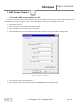
If you are using WinUSB, you will need the GUID defined on the driver’s .inf file:
GUID= 88BAE032-5A81-49f0-BC3D-A4FF138216D6
6.4 Command Set
When using the serial port, the commands are sent to the XScope in ASCII format, further data sent or received is in
binary. When using the USB interface, the commands are sent as CONTROL READ requests, where the packet’s request
byte is the command, and the packet’s Index and Value are additional parameters sent to the XScope. If the PC is
requesting data, it will be returned in the endpoint 0 IN buffer. Table 12 shows the XScope Interface Protocol Commands.