
User Manual

XScopes
User’s Manual
DS-XScopes-3.5 – December, 2014 Page | 22
2.6 Display Settings
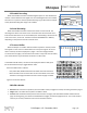
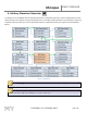
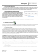
These menus control various characteristics of the display. Figure 45 shows the display menus.
Figure 45: Display menus
2.6.1 Persistent Display
When the persistent display is enabled, the waveform traces are not erased. The persistent display is useful as a
simple data logger or to catch glitches in the waveform. The persistent mode can also be used to make frequency plots in
combination with the AWG frequency sweep.
2.6.2 Line / Pixel Display
This menu item selects the drawing method.
Line: A line is drawn from one sample to the next.
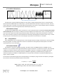
Pixel: A single pixel represents a sample. The pixel display is
useful at slow sampling rates or when used in combination with
the persistent mode. Figure 46 shows the pixel display.
2.6.3 Show scope settings
Toggles the display of the scope settings (Channel gain and time base).
2.6.4 Grid Type
There are 4 different grid types:
- No grid.
- Dots for each division: Vertical dots represent the scale divisions. Horizontal dots represent the time base
setting and the ground level of each channel.
- Vertical grid line follow trigger: Vertical dots represent the position of the trigger, the location of the vertical
dots follow the trigger position. Horizontal dots represent the time base setting and the ground level of each
channel.
- Dot graticule: The screen is filled with dots that represent the vertical and horizontal divisions.
2.6.5 Flip Display
The display orientation is flipped. This is useful when mounting the XScope on a panel, and the display’s orientations is
backwards.
2.6.6 Invert Display
When enabled, the display’s pixels are inverted (the display will have a white background).
Figure 46: Pixel Display