
User Manual

XScopes
User’s Manual
DS-XScopes-3.5 – December, 2014 Page | 19
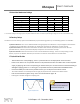
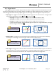
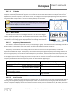
2.4.1.3 XY Mode
The XY mode changes the display from volts vs. time, to volts vs. volts. You can use XY mode to compare frequency
and phase relationships between two signals. The XY mode can also be used with transducers to display strain versus
displacement, flow versus pressure, volts versus current, or voltage versus frequency. Lissajous figures can be plotted
using the XY Mode. Component V/I curves can also be plotted, see section 8.5.
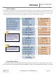
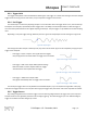
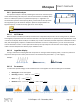
2.4.2 Meter Mode
The XScope can function as a dual digital voltmeter. The font used is bigger
in meter mode to facilitate reading. The available measurements in meter mode
are: Average Voltage (DC), Peak to Peak Voltage, Frequency, and Pulse counting.
A small trace of the analog signals is displayed below the voltage measurements.
2.4.2.1 Frequency Measurements
The device can measure frequencies on any channel (analog or digital). The measurements on the analog channels are
always shown, and the trigger source (see section 2.3) selects which digital channel to measure.
Frequency measurements on the analog channels are done using the FFT of the acquired data, so measured
frequencies have discrete steps. The frequency range is determined by the highest frequency of the analog channels. If
there is a high frequency on one channel and a low frequency on the other, the channel with the lowest frequency will
have low resolution. Frequency measurements with the FFT are best suited for analog signals. Frequency measurements
on the digital inputs are done counting the pulses on the pin over one second. The resolution of the measurement is 1Hz.
Frequency measurements with the Frequency counter are best suited for digital signals.
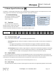
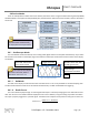
FFT (Analog channels)
Frequency Counter (Digital channels)
Maximum voltage range
-14V to 20V
Logic level range (or Ext. Trig -2.2V to 5.5V)
Maximum Frequency
500kHz
16MHz (or 12MHz on the Ext. Trig)
Resolution
Variable, depending on frequency
range. From 6.25Hz to 7.812kHz
1Hz
Signal is noisy, or is
mixed with other signals
Finds the fundamental frequency
Not suitable
Signal has a high offset
Still works
Stops working when the offset is above the
logic threshold.
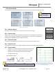
2.4.2.2 Pulse Counter
The device can count the number of pulses on a digital input. The counter will roll over after reaching 99,942,399. The
counting can be stopped by stopping the acquisition (K1 button on the main menu). Pressing any button will reset the
counter. A stopwatch displays the time since the Pulse Counter started, and can reach 255 hours, 59 minutes, 59 seconds.
Figure 35: Meter Mode
Figure 34: XY Mode
When using the XY modes with a Slow Sampling rate, activating the
ROLL mode will display a continuous “beam”.
Table 6: FFT vs. Frequency Counter
You can use the “Explore Wave” menu to move the graph vertically.