Gabotronics PO BOX 110332 Lakewood Rch, FL. 34211 www.gabotronics.com XScopes User’s Manual Main Features: Mixed Signal Oscilloscope: Simultaneous sampling of 2 analog and 8 digital signals. Arbitrary Waveform Generator with advanced sweep options on all the wave parameters. Protocol Sniffer: SPI, I C, UART Advanced Triggering System: Normal / Single / Auto / 2 Free, with many trigger modes; adjustable trigger level, and ability to view signals prior to the trigger.
XScopes User’s Manual About this manual This manual targets both novice and advanced users, providing a full resource for everyone. However, for a full understanding of the operation of the XScopes, the user should be familiar with the operation of a regular oscilloscope. The features documented in this manual are for units with firmware version 2.40+. Conventions XScope: Xprotolab, Xminilab, Xprotolab Portable or Xminilab Portable.
XScopes User’s Manual TABLE OF CONTENTS 1. General Overview....................................................................................................................................... 7 1.1 Xprotolab & Xminilab Pin Description .................................................................................................... 7 1.2 Xprotolab Portable and Xminilab Portable Overview ......................................................................... 8 1.2.1 Input Coupling Switch .........
XScopes User’s Manual 2.3.3 Trigger Hold .................................................................................................................................................... 17 2.3.4 Post Trigger ..................................................................................................................................................... 17 2.3.5 Trigger Source........................................................................................................................
XScopes User’s Manual 3.1 Input Selection ........................................................................................................................................ 23 3.2 Channel Position ..................................................................................................................................... 23 3.3 Invert Channel ......................................................................................................................................... 23 3.
XScopes 7. User’s Manual BMP Screen Capture ................................................................................................................................. 34 7.1 To send a BMP screen capture to a PC:.............................................................................................. 34 7.2 To send a BMP screen capture to Linux:.............................................................................................. 35 8. XScope’s Examples ...............................
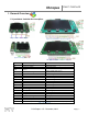
XScopes User’s Manual 1. General Overview 1.1 Xprotolab & Xminilab Pin Description K1 K2 K3 K4 K1 Figure 4: Front and Top Signals K2 K3 K4 Figure 3: Xminilab HW 2.1 & 2.2 Front Signals K1 K2 K3 K4 Figure 5: Back Signals Figure 6: Xminilab HW 2.3 Front Signals Name Description Comment +5V -5V +5V Input voltage -5V Output voltage GND Ground +3.3V Logic 0 Logic 1 Logic 2 Logic 3 Logic 4 Logic 5 Logic 6 Logic 7 EXT. T AWG CH2 CH1 PWR RX TX LNK +3.
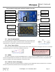
XScopes User’s Manual 1.2 Xprotolab Portable and Xminilab Portable Overview MENU / Power button K3 Input Coupling Switch Analog Inputs Digital Inputs K2 Arbitrary Waveform ON USB Port / Device Charging K1 External Trigger OFF Curve Tracer Switch Figure 7: Xprotolab Portable Curve Tracer Switch USB Port / Device Charging External Trigger Arbitrary Waveform Digital Inputs Analog Inputs MENU / Power button K1 K2 Input Coupling Switch K3 Figure 8: Xminilab Portable 1.2.
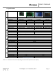
XScopes 1.3 Specifications Oscilloscope Logic Analyzer General Xprotolab AWG User’s Manual Microcontroller Display Type Display Size Display Life Time Device size Weight Interfaces Battery Active current1 Sleep current Logic Inputs Logic Input levels Input Pull Max. Sampling rate Buffer Size Frequency Counter Sniffer Protocols Analog Inputs Max. Sampling rate Analog Bandwidth Resolution Input Impedance Buffer size Input Voltage Range Vertical Sensitivity Analog Outputs Max.
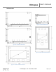
XScopes User’s Manual 1.4 Dimensions Figure 11: Xprotolab Dimensions Figure 12: Xminilab 2.1 & 2.2 Dimensions Figure 13: Xminilab 2.3 Dimensions Figure 14: Xprotolab-Portable Dimensions Figure 15: Xminilab-Portable Dimensions DS-XScopes-3.
XScopes User’s Manual 1.5 Absolute Maximum Ratings Parameter Supply Voltage (+5V) Analog Inputs1 Digital Inputs External Trigger Operating Temperature Storage Temperature Xprotolab & Xminilab Minimum Maximum -0.5 5.5 -30 30 -0.5 3.8 -3.5 6.8 -40 70 -40 80 Portable Variants Minimum Maximum N/A (Battery Powered) -180 180 -0.5 5.5 -3.5 6.8 -40 70 -40 80 Unit V V V V °C °C Table 3: Absolute Maximum Ratings 1. The maximum voltage on the analog inputs has only been tested to these limits.
XScopes User’s Manual 1.8 User Interface The K4 button is the MENU button, used to navigate thru all the menus. The K1 - K3 buttons action depend on the current menu. The green arrows represent the flow when pressing the MENU button. When the MENU button is pressed on the last menu, the device settings are saved and the menu goes back to the default. Figure 17 shows the main menus in blue and some secondary menus in yellow. Further ramifications are shown on the respective chapters.
XScopes User’s Manual 2. Mixed Signal Oscilloscope The XScope is a mixed signal oscilloscope; it has 2 analog channels and 8 digital channels. This chapter will focus on the analog signals. More information about the digital channels is presented in chapter 3. 2.1 Horizontal Settings The horizontal settings are controlled on the default menu. The menu is shown on figure 18. 2.1.1 Time Base The time base can be varied from 8µs/div to 50s/div. Table 4 shows all the possible time bases.
XScopes User’s Manual 2.2 Vertical Settings The analog channel controls are discussed in this section. Figure 19 shows the Vertical menu flow. CH1 and CH2 have identical settings. Figure 19: Vertical menus 2.2.1 Disable Channel Any channel can be disabled; this is useful to reduce clutter on the display. 2.2.2 Channel Gain Table 5 shows the possible gain settings for the analog channels. One gain division consists of 16 pixels.
XScopes User’s Manual 2.3 Trigger Settings The XScope has an advance triggering system, it has most of the trigger controls of a professional oscilloscope. Figure 24 shows the trigger menus. Figure 24: Trigger menus 2.3.1 Trigger Types There are four different trigger types, which determine when to display the trace on the screen: Normal: Trace only when the trigger event occurs. Single: Only one trace is displayed when the trigger event occurs.
XScopes User’s Manual 2.3.2 Trigger Modes Three triggering modes are available: Edge, Window, and Slope. The Edge and Slope have selectable direction. When selecting an analog trigger source, the trigger direction is changed in the “Adjust Trigger Level” menu, by moving up or down the trigger level. When selecting a digital trigger source, the trigger direction is toggled on every button press. Edge Trigger: The trigger occurs when the signal crosses the trigger level in a certain direction.
XScopes User’s Manual 2.3.3 Trigger Hold The trigger hold specifies a time to wait before detecting the next trigger. It is useful when the signal can have multiple trigger events occurring close to each other, but you only want to trigger on the first one. 2.3.4 Post Trigger The oscilloscope is continuously acquiring samples in a circular buffer. Once the trigger event occurs, the oscilloscope will acquire more samples, specified by the Post Trigger value.
XScopes User’s Manual 2.4 Device Modes There are multiple device modes that can be selected; the menus shown on figure 32 allow selecting the Scope Mode, the Meter Mode or the Spectrum Analyzer Mode (FFT). Another device mode is the Protocol Sniffer, which is discussed in section 3.8. In the “Mode Menu”, press K1 and K3 simultaneously, to display both the Scope and FFT. Figure 32: Device mode menus 2.4.1 Oscilloscope Mode This is the default mode of the XScope.
XScopes 2.4.1.3 User’s Manual XY Mode The XY mode changes the display from volts vs. time, to volts vs. volts. You can use XY mode to compare frequency and phase relationships between two signals. The XY mode can also be used with transducers to display strain versus displacement, flow versus pressure, volts versus current, or voltage versus frequency. Lissajous figures can be plotted using the XY Mode. Component V/I curves can also be plotted, see section 8.5.
XScopes User’s Manual 2.4.3 Spectrum Analyzer The spectrum analyzer is done by calculating the Fast Fourier Transform (FFT) of the selected analog channels (or the channel math functions if enabled). When the FFT is enabled, the spectrum is plotted as frequency vs. magnitude. The horizontal axis represents the frequency (Hertz), and the vertical axis represents the magnitude. Figure 36 shows the XScope in Spectrum Analyzer Mode. The Nyquist frequency is shown on the top right corner of the display.
XScopes User’s Manual 2.5 Cursors You can measure waveform data using cursors. Cursors are horizontal and vertical markers that indicate X-axis values (usually time) and Y-axis values (usually voltage) on a selected waveform source. The position of the cursors can be moved on the respective menu. Figure 41 shows the cursor menus. Figure 41: Cursor menus 2.5.1 Vertical Cursors Time interval measurements are made with a pair of time markers.
XScopes User’s Manual 2.6 Display Settings These menus control various characteristics of the display. Figure 45 shows the display menus. Figure 45: Display menus 2.6.1 Persistent Display When the persistent display is enabled, the waveform traces are not erased. The persistent display is useful as a simple data logger or to catch glitches in the waveform. The persistent mode can also be used to make frequency plots in combination with the AWG frequency sweep. 2.6.
XScopes User’s Manual 3. Logic Analyzer and Protocol Sniffer The XScope has an 8 bit logic analyzer and can do sniffing on standard protocols: I2C, UART and SPI. The logic inputs are 3.3V level, only the Portable devices are 5V tolerant. If you need to connect 5V signals to the logic analyzer, you could add a 3K resistor in series with the signal, or use a 5V to 3.3V level converter chip. Figure 47 shows the logic menus. Figure 47: Logic Analyzer Menus 3.
XScopes User’s Manual 3.5 Parallel Decoding Shows the hexadecimal value of the 8 bit digital input lines. The hexadecimal number is shown below the last digital trace. If all the 8 digital traces are enabled, then there is no space to show the parallel decoding. Figure 48 shows an example of the parallel decoding with 4 logic lines enabled. Figure 48: Parallel Decoding 3.6 Serial Decoding Shows the hexadecimal value of the stream of bits on each channel.
XScopes User’s Manual 3.9 I2C Sniffer Connect SDA to Bit 0, SCL to Bit 1 The XScope implements the I2C sniffing in a bit-bang fashion. The maximum tested clock frequency is 400kHz (Standard I2C Fast Speed). As the data is decoded, the data in HEX will appear on the screen, accompanied by a symbol: When the Master initiates a read, < is an ACK and ( is a NACK When the Master initiates a write, > is an ACK and ) is a NACK Subsequent data in the frame will be accompanied by + for ACK or a - for NACK.
XScopes User’s Manual 4. Arbitrary Waveform Generator The XScope has an embedded arbitrary waveform generator. The waveform generator output is independent from the data acquisition and is always running in the background. You can adjust all the parameters of the waveform: frequency, amplitude, offset and duty cycle. You can sweep the frequency, amplitude and duty cycle. Figure 53 shows the AWG Menus.
XScopes User’s Manual 4.1 Predefined Waveforms Sine Wave Square Wave Triangle Wave Exponential Periodic Noise Custom Wave * Table 8: AWG Preprogrammed Waveforms The XScope can output the following waveforms: Sine, Square, Triangle and Exponential. There is a “Periodic Noise” option that fills the AWG buffer with random data, it is periodic because the same data is output over and over, but each time the Noise wave is selected, new random data will be generated.
XScopes User’s Manual 5. PC Interface The device can interface with a PC (Linux, Mac, or Windows). The device needs to be updated with the latest firmware. The source code for the PC interface is open source under the GPLv3 license and is available on GitHub. 5.1 Connecting the device The XScope can communicate to a PC thru the USB port. When the application starts, it will try to connect automatically.
XScopes User’s Manual 5.2 Custom AWG Waveform You can define your own waveforms for the AWG. On the Waveform Generator tab, click “Open CSV” and select your CSV file, then click “Save as Custom”, the waveform will be permanently saved in the device’s EEPROM memory. When creating a CSV file, the range of the data must be [-127, 127], and there should be only 256 numbers. 5.
XScopes Index 0 1 2 3 4 5 6 7 8 9 10 11 12 13 14 15 16 17 18 19 20 21 22 23 24 25 26 27 28 29 30 31 32 33 34 35 36 37 38 39 40 41 42 43 Name Srate CH1ctrl CH2ctrl CHDctrl CHDmask Trigger Mcursors Display MFFT Sweep Sniffer MStatus CH1gain CH2gain HPos VcursorA VcursorB Hcursor1A Hcursor1B Hcursor2A Hcursor2B Thold Tpost L Tpost H Tsource Tlevel Window1 Window2 Ttimeout CH1pos CH2pos CHDpos CHDdecode Sweep1 Sweep2 SWSpeed AWGamp AWGtype AWGduty AWGoffset desiredF LLB desiredF LHB desiredF HLB desiredF HHB
XScopes User’s Manual 6.2.
XScopes Name MFFT Index 8 Sweep Index 9 Sniffer Index 10 MStatus Index 11 Bits Bit 0: Hamming Window Bit 1: Hann Window Bit 2: Blackman Window Bit 3: Vertical Log Bit 4: IQ FFT Bit 5: Scope Mode Bit 6: XY Mode Bit 7: FFT Mode Bit 0: Acceleration Direction Bit 1: Accelerate Sweep Bit 2: Sweep Direction Bit 3: Ping Pong Mode Bit 4: Sweep Frequency Bit 5: Sweep Amplitude Bit 6: Sweep Offset Bit 7: Sweep Duty Cycle Bit 0: Baud 0 Bit 1: Baud 1 Bit 2: Baud 2 Bit 3: Uart 0 Bit 4: Uart 1 Bit 5: Parity Mode / S
XScopes Command a b Description Request firmware version Writes a byte to the XScope’s Settings, at the specified index. If the Index is below 14, the updatemso bit is automatically set. If the Index is above 34, the updateawg is automatically set. c Sets the desired AWG Frequency (32bits).
XScopes User’s Manual 7. BMP Screen Capture 7.1 To send a BMP screen capture to a PC: You can send a screen capture of the XScope to your PC using HyperTerminal. All the screen captures bitmaps in this manual where generated using this method. The screen capture is done thru the XScope’s serial port. Open HyperTerminal. Enter a name for a new connection (example: scope). Enter the COM port where the device is connected.
XScopes User’s Manual Figure 57: Receive File Settings Enter a file name with a BMP extension and press OK 7.2 To send a BMP screen capture to Linux: Create the following script and save as capture.sh: capture.sh echo "Please enter filename. e.g capture.bmp" read name stty -F $1 115200 rx -c $name < $1 > $1 To use, make the script executable with “chmod +x capture.sh”. Then enter “./capture.sh” into a terminal followed by the serial device for example “./capture.sh /dev/ttyUSB0”.
XScopes User’s Manual 8. XScope’s Examples 8.1 Resistor Voltage Divider 1) Build the circuit shown on figure 59. 2) Set the device to Meter mode 3) You should see similar voltages as shown on figure 60. Figure 59: Resistor divider Figure 60: Meter mode Theory of operation: The circuit is a voltage divider, where Vin is 5V, and Vout is the voltage at CH2: 𝑽𝒐𝒖𝒕 = 𝑽𝒊𝒏∗𝑹𝟏 𝑹𝟏+𝑹𝟐 8.2 Measurement of an RC time constant 1) 2) 3) 4) 5) 6) 7) 8) 9) 10) 11) 12) Build the circuit shown on figure 62.
XScopes User’s Manual 8.4 BJT Amplifier 1) Build the circuit shown on figure 69. 2) Set the time base to 2ms/div 3) Move the position on both channels all the way down (GND reference grid is at the bottom of the screen). Figure 68: BJT Measurements Figure 69: Amplifier circuit 4) Set CH1 to 0.32V/div, Set CH2 to 1.28V/div. 5) Set the AWG to Sine wave, 125Hz, 0.250V amplitude. 6) Increase the AWG offset until the CH2 wave is centered on the display. The display should look like figure 68.
XScopes User’s Manual 9. Firmware Updating This guide will show how to update the firmware on your AVR XMEGA based device. There are two updating methods; the first method requires an external programmer. You can use either method depending on your needs. 9.1 Firmware upgrade using an external programmer 9.1.
XScopes User’s Manual 9.2 Firmware upgrade using the bootloader 9.2.1 Tools required Standard USB type A to micro USB cable. Windows: o Atmel’s FLIP software: http://www.atmel.com/tools/FLIP.aspx. o Flip Manual with driver installation procedure: http://www.atmel.com/Images/doc8429.pdf. Linux: AVRDude version 6.1 or above: http://www.nongnu.org/avrdude/ HEX and EEP files for the device, found on the product's page (Look for the HEX icon). 9.2.
XScopes 10. User’s Manual Frequently Asked Questions 1) What tools do I need to develop my own programs on the XScope? If you don’t need debugging capabilities, only a regular cable is needed to program the device. If you want to be able to debug your code, you need an external debugger, such as the AVR JTAGICE mkII or the AVR ONE!.
XScopes User’s Manual 10) The source code says "evaluation version", can I get the full version? The full source code can be found on GitHub: https://github.com/ganzziani/XScopes-Firmware 11) I tried updating the firmware using the USB bootloader. It didn’t work and now the device does not start. The bootloader should still be functional. Try resetting the computer and try the procedure again, step by step.
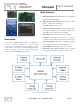
XScopes 12. User’s Manual XScope Design The hardware and firmware are open source under the GPLv3 license. The firmware for all the Xscopes is available on GitHub: https://github.com/ganzziani/XScopes-Firmware 12.1 System Architecture The XScope uses many resources and peripherals of the XMEGA microcontroller. Figure 76 shows the XScope’s Architecture block diagram. Figure 77 shows the Frequency Counter block diagram.
XScopes 12.2 User’s Manual Schematics Figure 78: Xprotolab Schematic DS-XScopes-3.
www.gabotronics.