
User Manual


Specifications
Input voltage: 10.2-14Vdc.
Input current (excl. heater): 100mA @ nom. 12Vdc.
Operating temperature: -13 to 158 F (-25 to 70 C)
without heater.
Operating humidity: 15 to 90%, non-condensing.
Maximum read range: 5" (125mm).
Approvals: EN300330, EN301489
°°
5
Using the Reader
4
Reader Connections
9600-0531. Installation and User Instructions for S849 Readers,
Issue 1.0 16th Decemmber 2009. G4S Technology, 2009.
All trademarks acknowledged. HID is a registered trademark of HID
Corporation.
FCC Notice: This device complies with Part 15 of the FCC Rules.
Operation is subject to the following two conditions: (1) This device
may not cause harmful interference, and (2) this device must accept
any interference received, including interference that may cause
undesired operation.
Any unauthorized modification to this device may void the authority of
the user to operate it.
©
Present the card face-on to the reader until you hear "bleep". Cards can be presented in rapid
succession; there is no need to wait for the green or red LED to extinguish efore presenting another.
a
b
If the reader has been enabled for user-code mode at the controller, you can gain access by pressing
the # key, entering your card number, then pressing the * key.
If the amber LED flashes, enter your PIN. If you make a
mistake, the red LED is lit for a moment, then the flashing
amber prompts you to try again.
These auxiliary LED indicators can be configured to
operate in conjunction with conditional commands.
When this LED is lit, the lock is released and you may
open the door.
Green (access
granted) LED
Red (access
denied) LED
Flashing amber
(PIN) LED
Alarm LED
Switch LED
This is lit if you do not have access rights to gain entry, or
if the reader could not read your card (in this case, move
the card away, then present it again).
About the Reader LEDs
}
Connect shield at
controller end only
(attach to case)
TX-
Reader
Twisted pairs
(use Belden)
TX+
0V
TX-
RX+
RX-
+V
Do not use
Do not use
Do not use
Do not use
12Vdc
TX+
RX+
RX-
0V
Note: To configure the
reader as a 20mA reader,
connect the jumper
across the center and
"C/L" pins of LK1.
WE C/L
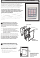
Current Loop Reader Connections
12Vdc
Connect shield at
controller end only
(attach to case)
Apply 0V to
activate door-
Green
Red
Data 0
Data 1
0V
Reader
Gn
0V
0s
Do not use
Do not
+V
Bz
1s
Do not use
Rd
Note: To configure the
reader as a Wiegand
reader, connect the
jumper across the center
and "WE" pins of LK1.
WE C/L
Wiegand Reader Connections