
User Manual

Using the Reader
6
Reader Configuration
5
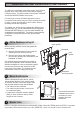
Present the card face-on to the reader until you hear a "bleep". Cards can be presented in rapid succession;
there is no need, for example, to wait for "UNLOCKED" to disappear before presenting another.
If the reader has been enabled for user-code mode at the controller, you can gain access by pressing the #
key, entering your card number, then pressing the * key.
9600-0539. Installation and User Instructions for S843 Readers,
Issue 1.0 14th April 2010. G4S Technology Limited 2010.
FCC Notice: This device complies with Part 15 of the FCC Rules.
Operation is subject to the following two conditions: (1) This device
may not cause harmful interference, and (2) this device must accept
any interference received, including interference that may cause
undesired operation.
Any unauthorized modification to this device may void the authority of
the user to operate it. This device complies with the provisions of
European Directive 1999/5/EC. All trademarks acknowledged. Philips
and MIFARE are registered trademarks of Philips Electronics N.V.
©
About the Reader Messages
}
READY –
UNLOCKED – The lock is released and you may open the door.
ACCESS DENIED & LOCKED – You do not have access rights to gain entry, or the reader
did not read your card properly (in this case, present it again).
ENTER PIN – Enter your PIN. If you make a mistake, the message INCORRECT PIN is
momentarily displayed, followed by ENTER PIN, to prompt you to try again.
CARD PIN AND # – Enter the DESfire card PIN, then press # if the PIN is less than 8 digits.
The reader is waiting for a valid card to be presented.
(Flashing or steady) – These auxiliary indicators can be configured to operate in
conjunction with conditional commands.
Specifications
Input voltage: 10.2-14Vdc.
Input current (excl. heater): 190mA @ nom. 12Vdc.
Operating temperature: -4 to 158 F (-20 to 70 C)
without heater.
Operating humidity: 15 to 90%, non-condensing.
Maximum read range: 1" (25mm).
Approvals: EN50133, 1999/5/EC, IP65.
° °
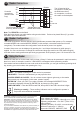
0V
RX+
RX-
TX+
TX-
12V
Reader
Controller
connections
(20mA current
loop)
The I/O terminal is for
connection to a RIM (see
the RIM Instructions).
On completion, re-secure
the reader to the backplate.
0V
TX+
Do not use
TX-
I/0
RX+
RX-
+V
The reader supports the first two different card types/formats presented after power-up. For example,
encoded MIFARE and encoded MIFARE DESfire (in this example, unencoded cards would not be
recognized). The reader enters this configuration mode whenever power is re-applied.
A reader Setup menu can be displayed by pressing the * and # keys simultaneously while power is
applied. You can use the menu to change the contrast and language used for the LCD (default English),
and view the two card types/formats previously programmed. At the prompts, press * for No and # for Yes.
Reader Connections
4
Slide the ferrite sleeve onto cable before wiring terminal block. Ferrite to be placed 50mm (2") up cable
and held in place with cable ties.
Note: The FERRITE must be fitted!
Connect shield at controller
end only (attach to case).
Twisted pairs (use
Belden 9503 cable).