
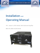
Installation and Operating Manual

Page | 9
OPERATION:
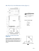
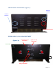
Refer to Figure 3 & 3a for adjustment access location, connectors and labels.
Variable Step Attenuator
BDA gain can be reduced by up to 30 dB in 2 dB steps using the variable step
attenuator. Gain adjustment is made with rotary switches accessible via the access
door on the BDA enclosure. Arrows on the shafts of these switches point to the value
of attenuation selected. BDA gain can be determined by subtracting the attenuation
value from the gain reported on the BDA Test Data Sheet for that side of the unit. The
attenuators are labeled for Uplink and Downlink.
ALC (Automatic Level Control)
To minimize intermodulation products, each amplifier in the BDA contains an ALC
feedback loop. The ALC circuit senses the output power and automatically limits it to
the factory preset level of +33 dBm UL and +33 dBm DL.
ALC function is located in each power amplifier. A red LED indicator located on the
Front main panel (see figure 3) illuminates when output power meets or exceeds the
ALC preset point.
To establish proper operating gain on the Uplink and Downlink sides, start with the
Downlink. Observe the red LED indicator on the Downlink amplifier. Units are shipping
with maximum attenuation. Decrease attenuation one step at a time until the red LED
is lit. Then, using the Downlink step attenuator, increase the attenuation until the red
LED goes off. Repeat the process for the Uplink. . This setup should be done under
RF signal transmit for either path the level indicator is accurate to +/- 0.4 dB of the
ALC set point.
G-Wave BDAs will automatically limit the output power of the system to the
established ALC setting of the unit, +33 dBm. An LED indicator will illuminate to
inform the operator that maximum output signal has been achieved during the
gain adjustment process.
Note: Operation of BDA-LTE/LABC-33/33-90-AB at maximum gain with greater
than -40 dBm average power incidents on the MOBILE or BASE ports could
cause damage to the BDA.