
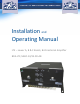
Installation and Operating Manual

Page | 6
RFEXPOSUREWARNING‐INDUSTRYCANADA:
In order to comply with the IC RF exposure requirements, the BDA-LTE/LABC-33/33-90-AB
antenna installation must comply with the following:
The outdoor antenna (Yagi type or similar directional antenna if off air donor signal used) must
be installed so as to provide a minimum separation distance of 64 cm between the antenna
and persons within the area. (This assumes a typical antenna with gain of [7.5 dBi, VSWR ≤
1.5:1, Zo= 50 ohms).
The indoor antenna (Omni directional) must be installed so as to provide a minimum
separation distance of at least 33 cm between the indoor antenna connected to the RF
booster and the human user’s body within the area. (This assumes a typical wide-beam type
antenna with gain of 0-2 dBi, VSWR ≤ 2:1, Zo= 50 ohms,).
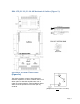
CONNECTIONS:
The BDA AC power is accepted through a circular 3-wire female plug with phase, neutral and
ground leads. The AC power is wired to a high efficiency DC switching power supply which is CE
and UL approved. The power supply runs the amplifiers and the LED indicators. The metal
enclosure of the BDA is connected to ground.
A 7-pin circular connector provides failure and Oscillation Detect alarms output dry contacts,
Normally Open and Normally Closed (see diagrams on page 8).
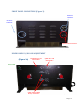
The RF connections are made via two type “N” female connectors. The RF connector labeled
“BASE” must be connected to the antenna pointing towards the base station. The RF
connection labeled “MOBILE” must be connected to the antenna / passive DAS facing the
area to be covered by the BDA.
The RF connections must be made through cables with characteristic impedance of 50 ohms.
The isolation between the base station antenna and the mobile antenna should be at
least 12 dB higher than the BDA gain.
Isolation less than this value can cause gain
ripple across the band. Isolation equal to or less than the BDA gain will give rise to
oscillations which will saturate the amplifiers and possibly cause damage to the BDA.